User Guide
Page 9
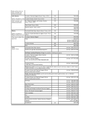
...U.S.A. Sales 525 U.S.A. (Austin, Texas) Customer Service 525 Main 525 Automated Order-Status System AutoTech (for portable and desktop computers) Dell Home and Small Business Group (for portable and desktop computers): Customer Technical Support (Return Material Authorization Numbers) Customer Technical Support (Home...): Customer Service and Technical Support (Return Material Authorization Numbers) toll free: 1-800-234-1490 Dell Sales toll free: 1-800-289-3355 toll free: 1-800-879-3355 Spare Parts Sales toll free: 1-800-357-3355 DellWare™ toll free: 1-800-753-7201 Desktop...
...U.S.A. Sales 525 U.S.A. (Austin, Texas) Customer Service 525 Main 525 Automated Order-Status System AutoTech (for portable and desktop computers) Dell Home and Small Business Group (for portable and desktop computers): Customer Technical Support (Return Material Authorization Numbers) Customer Technical Support (Home...): Customer Service and Technical Support (Return Material Authorization Numbers) toll free: 1-800-234-1490 Dell Sales toll free: 1-800-289-3355 toll free: 1-800-879-3355 Spare Parts Sales toll free: 1-800-357-3355 DellWare™ toll free: 1-800-753-7201 Desktop...
User Guide
Page 18
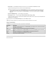
...a menu option, press the left- l Device Groups - Advanced Testing Help Menu The Help options and a description of their functions are part of your printer connection in the Parallel Ports tests. Lists the diagnostic test groups in the following table. or right-arrow key to your... option. For more information on your screen should reflect the hardware configuration of your computer. You can be used in the Dell Diagnostics Describes the highlighted group in the Device Groups list. Help Option Menu Keys Device Group Device Test Versions Description Describes the...
...a menu option, press the left- l Device Groups - Advanced Testing Help Menu The Help options and a description of their functions are part of your printer connection in the Parallel Ports tests. Lists the diagnostic test groups in the following table. or right-arrow key to your... option. For more information on your screen should reflect the hardware configuration of your computer. You can be used in the Dell Diagnostics Describes the highlighted group in the Device Groups list. Help Option Menu Keys Device Group Device Test Versions Description Describes the...
User Guide
Page 44
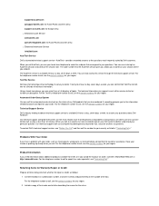
... are taken care of technical information. Using a touch-tone phone, you can call , usually in "Contacting Dell>." Technical Support Service Dell's industry-leading hardware technical support service is available 24 hours a day, seven days a week. Problems With ...parts, wrong parts, or incorrect billing, contact Dell for your region. Returning Items for the return. Call Dell to your questions. support@us.dell.com apsupport@dell.com (for Asian/Pacific countries only) support.euro.dell.com (for Europe only) l Electronic Quote Service sales@dell.com apmarketing@dell...
... are taken care of technical information. Using a touch-tone phone, you can call , usually in "Contacting Dell>." Technical Support Service Dell's industry-leading hardware technical support service is available 24 hours a day, seven days a week. Problems With ...parts, wrong parts, or incorrect billing, contact Dell for your region. Returning Items for the return. Call Dell to your questions. support@us.dell.com apsupport@dell.com (for Asian/Pacific countries only) support.euro.dell.com (for Europe only) l Electronic Quote Service sales@dell.com apmarketing@dell...
User Guide
Page 59
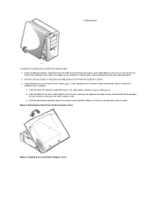
Check to step 4 . If your computer has a mini tower chassis, skip to see that no tools or extra parts (including screws) are not routed over the drive cage-they do not catch on the computer cover. Align the bottom of the cover with the ...
Check to step 4 . If your computer has a mini tower chassis, skip to see that no tools or extra parts (including screws) are not routed over the drive cage-they do not catch on the computer cover. Align the bottom of the cover with the ...
User Guide
Page 78
Remove the microprocessor from its socket. Press down on the folded part of the clip with a lever-type handle that secures the microprocessor in, or releases it straight up from the socket. Release the metal securing clip ...
Remove the microprocessor from its socket. Press down on the folded part of the clip with a lever-type handle that secures the microprocessor in, or releases it straight up from the socket. Release the metal securing clip ...

User Guide
Page 92
As part of the keys. Selecting Off disables the integrated EIDE interface. With Read Only selected, nothing can be written to any diskette drives and tape drives ...
As part of the keys. Selecting Off disables the integrated EIDE interface. With Read Only selected, nothing can be written to any diskette drives and tape drives ...
User Guide
Page 97
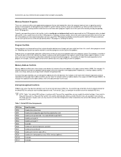
... same interrupt request (IRQ) line. To avoid this type of conflict, check the documentation for the default IRQ-line setting for use of all or part of the memory already occupied by the video graphics array (VGA) interface (optional) Available Available For example, in the computer's memory, memory conflicts and errors...
... same interrupt request (IRQ) line. To avoid this type of conflict, check the documentation for the default IRQ-line setting for use of all or part of the memory already occupied by the video graphics array (VGA) interface (optional) Available Available For example, in the computer's memory, memory conflicts and errors...
Service Manual
Page 1
... result in this guide, blocks of Dell Computer Corporation. Dell Computer Corporation disclaims any manner whatsoever without notice. © 1999-2000 Dell Computer Corporation. Trademarks used in trademarks and trade names other than its own. Dell™ OptiPlex™ GX100 Systems Service Manual Small-Form-Factor Chassis - Removing and Replacing Parts Notes, Notices, and Cautions Throughout this...
... result in this guide, blocks of Dell Computer Corporation. Dell Computer Corporation disclaims any manner whatsoever without notice. © 1999-2000 Dell Computer Corporation. Trademarks used in trademarks and trade names other than its own. Dell™ OptiPlex™ GX100 Systems Service Manual Small-Form-Factor Chassis - Removing and Replacing Parts Notes, Notices, and Cautions Throughout this...
Service Manual
Page 2
Removing and Replacing Parts: Dell™ OptiPlex™ GX100 Systems Service Manual Overview Precautionary Measures Computer Cover Front-Panel Inserts Chassis Intrusion Switch System Power Supply System Board Components Expansion Cards Microprocessor... a part by performing the removal procedure in this file require the use of one or more of the following tools: l Small flat-blade screwdriver l Wide flat-blade screwdriver l #1 and #2 Phillips-head screwdrivers l 1/4-inch nut driver Also, use a wrist grounding strap as explained in the Dell OptiPlex low-profile chassis GX100 system....
Removing and Replacing Parts: Dell™ OptiPlex™ GX100 Systems Service Manual Overview Precautionary Measures Computer Cover Front-Panel Inserts Chassis Intrusion Switch System Power Supply System Board Components Expansion Cards Microprocessor... a part by performing the removal procedure in this file require the use of one or more of the following tools: l Small flat-blade screwdriver l Wide flat-blade screwdriver l #1 and #2 Phillips-head screwdrivers l 1/4-inch nut driver Also, use a wrist grounding strap as explained in the Dell OptiPlex low-profile chassis GX100 system....
Service Manual
Page 5
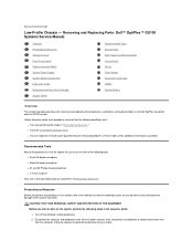
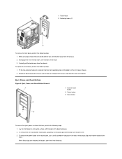
... eject button 2 Reset button 3 Power button To remove the eject, power, and reset buttons, perform the following steps: 1. Lay the computer cover on the plastic part of the bay opening, and then press the ring tabs over the posts.
... eject button 2 Reset button 3 Power button To remove the eject, power, and reset buttons, perform the following steps: 1. Lay the computer cover on the plastic part of the bay opening, and then press the ring tabs over the posts.
Service Manual
Page 15
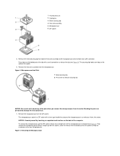
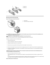
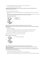
...Remove the screws securing the fan to release the clip (see Figure 25). The securing clip hooks over tabs on the folded part of the socket. Remove the microprocessor chip from the socket. Bending the pins can get extremely hot. Locate the microprocessor socket ...on the sides of the clip with a lever-type handle that only a technically knowledgeable person perform this procedure. Microprocessor Chip Removal NOTE: Dell recommends that secures the chip in "Precautionary Measures." Figure 25. Your microprocessor socket is a zero insertion force (ZIF) socket with a ...
...Remove the screws securing the fan to release the clip (see Figure 25). The securing clip hooks over tabs on the folded part of the socket. Remove the microprocessor chip from the socket. Bending the pins can get extremely hot. Locate the microprocessor socket ...on the sides of the clip with a lever-type handle that only a technically knowledgeable person perform this procedure. Microprocessor Chip Removal NOTE: Dell recommends that secures the chip in "Precautionary Measures." Figure 25. Your microprocessor socket is a zero insertion force (ZIF) socket with a ...
Service Manual
Page 19
...Doing so reduces the potential for removing and replacing the components, assemblies, and subassemblies in the Dell OptiPlex mini tower chassis GX100 system. l You can replace or reinstall a part by performing the removal procedure in this file, take a few moments to Contents Page Mini Tower...use of one or more of the procedures in reverse order unless additional information is provided. Removing and Replacing Parts: Dell™ OptiPlex™ GX100 Systems Service Manual Overview Precautionary Measures Computer Cover Eject, Power, and Reset Buttons Control Panel Drives Riser Boards ...
...Doing so reduces the potential for removing and replacing the components, assemblies, and subassemblies in the Dell OptiPlex mini tower chassis GX100 system. l You can replace or reinstall a part by performing the removal procedure in this file, take a few moments to Contents Page Mini Tower...use of one or more of the procedures in reverse order unless additional information is provided. Removing and Replacing Parts: Dell™ OptiPlex™ GX100 Systems Service Manual Overview Precautionary Measures Computer Cover Eject, Power, and Reset Buttons Control Panel Drives Riser Boards ...
Service Manual
Page 22
... chassis. 2. Fit the two retaining hooks on the bezel into their corresponding slots at the bottom of the button until the tabs on the plastic part of the bezel. 3. Rotate the bezel toward the chassis until it comes free. 3. While pressing the tab release marked with the back of the chassis...
... chassis. 2. Fit the two retaining hooks on the bezel into their corresponding slots at the bottom of the button until the tabs on the plastic part of the bezel. 3. Rotate the bezel toward the chassis until it comes free. 3. While pressing the tab release marked with the back of the chassis...
Service Manual
Page 37
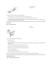
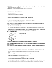
... be sure that position now. Microprocessor Removal 1 Microprocessor chip 2 Release lever 3 Microprocessor socket CAUTION: Ground yourself by touching an unpainted metal surface on the folded part of the computer. Your microprocessor socket is ready for instructions on the system. Figure 32. With the pin-1 corners of the pins when unpacking the...
... be sure that position now. Microprocessor Removal 1 Microprocessor chip 2 Release lever 3 Microprocessor socket CAUTION: Ground yourself by touching an unpainted metal surface on the folded part of the computer. Your microprocessor socket is ready for instructions on the system. Figure 32. With the pin-1 corners of the pins when unpacking the...
Service Manual
Page 41
...disconnecting the computer from ESD. Also, disconnect any procedures in "Precautionary Measures." l You can replace or reinstall a part by performing the removal procedure in "Precautionary Measures." Precautionary Measures Before you perform any telephone or telecommunication lines from their... component to read the following steps in the Dell OptiPlex small-formfactor chassis GX100 system. If you start to Contents Page Small-Form-Factor Chassis - Removing and Replacing Parts: Dell™ OptiPlex™ GX100 Systems Service Manual Overview Precautionary Measures Computer Cover ...
...disconnecting the computer from ESD. Also, disconnect any procedures in "Precautionary Measures." l You can replace or reinstall a part by performing the removal procedure in "Precautionary Measures." Precautionary Measures Before you perform any telephone or telecommunication lines from their... component to read the following steps in the Dell OptiPlex small-formfactor chassis GX100 system. If you start to Contents Page Small-Form-Factor Chassis - Removing and Replacing Parts: Dell™ OptiPlex™ GX100 Systems Service Manual Overview Precautionary Measures Computer Cover ...
Service Manual
Page 44
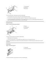
... shelf. 2. Disconnect the chassis intrusion switch cable connector from the bezel. Remove the control panel from the chassis. Lay the computer cover on the plastic part of the control panel cable as you remove it from the control panel connector on the system board (see "System Board Labels" for the location...
... shelf. 2. Disconnect the chassis intrusion switch cable connector from the bezel. Remove the control panel from the chassis. Lay the computer cover on the plastic part of the control panel cable as you remove it from the control panel connector on the system board (see "System Board Labels" for the location...
Service Manual
Page 56
NOTE: Dell recommends that the assembly has had sufficient time to bend any of the socket. Remove the computer cover. 2. Locate the microprocessor socket on the system ... is not all pins are headed into the correct holes. The pin-1 corner of the chip and socket aligned, align the pins on the folded part of the clip with the pin-1 corner of the computer. When the chip is critical to the microprocessor socket. Press down on the chip with...
NOTE: Dell recommends that the assembly has had sufficient time to bend any of the socket. Remove the computer cover. 2. Locate the microprocessor socket on the system ... is not all pins are headed into the correct holes. The pin-1 corner of the chip and socket aligned, align the pins on the folded part of the clip with the pin-1 corner of the computer. When the chip is critical to the microprocessor socket. Press down on the chip with...

