
Owner's Manual - Mini Tower
Page 3
... (WLAN) Card 9 Removing the Front Bezel...9 Installing the Front Bezel...10 Removing the Expansion Card...10 Installing the Expansion Card...11 Memory Module Guidelines...11 Removing the Memory...11 Installing the Memory...12 Removing the Coin-Cell Battery...12 Installing the Coin-Cell Battery...13 Removing the Hard Drive...13 Installing the Hard...
... (WLAN) Card 9 Removing the Front Bezel...9 Installing the Front Bezel...10 Removing the Expansion Card...10 Installing the Expansion Card...11 Memory Module Guidelines...11 Removing the Memory...11 Installing the Memory...12 Removing the Coin-Cell Battery...12 Installing the Coin-Cell Battery...13 Removing the Hard Drive...13 Installing the Hard...

Owner's Manual - Mini Tower
Page 11
... in the connector on the system board and press down on the memory retaining tabs on each side of the memory modules, and lift the memory modules out of the slowest installed memory modules. Removing the Memory 1. Press down until secured. 2. Follow the procedures in Before Working... Inside Your Computer. 2. Install the cover. 4. Follow the procedures in After Working Inside Your Computer. Remove the cover. 3. Memory Module Guidelines To ensure optimal performance of different sizes can be installed beginning with single or dual-rank modules, the quad-rank modules ...
... in the connector on the system board and press down on the memory retaining tabs on each side of the memory modules, and lift the memory modules out of the slowest installed memory modules. Removing the Memory 1. Press down until secured. 2. Follow the procedures in Before Working... Inside Your Computer. 2. Install the cover. 4. Follow the procedures in After Working Inside Your Computer. Remove the cover. 3. Memory Module Guidelines To ensure optimal performance of different sizes can be installed beginning with single or dual-rank modules, the quad-rank modules ...

Owner's Manual - Mini Tower
Page 12
... b) expansion card(s) 3. Install the cover. 4. Follow the procedures in the system-board connector. 2. Locate the coin-cell battery on the memory module until the release tabs spring back to pop-up from the socket and lift the coin-cell battery out of the computer. 12 Removing... the release latch away from the battery to allow the battery to secure them in Before Working Inside Your Computer. 2. Installing the Memory 1. Align the notch on the memory-card with the tab in After Working Inside Your Computer. Press down on the system board. 4. Follow the procedures in place. ...
... b) expansion card(s) 3. Install the cover. 4. Follow the procedures in the system-board connector. 2. Locate the coin-cell battery on the memory module until the release tabs spring back to pop-up from the socket and lift the coin-cell battery out of the computer. 12 Removing... the release latch away from the battery to allow the battery to secure them in Before Working Inside Your Computer. 2. Installing the Memory 1. Align the notch on the memory-card with the tab in After Working Inside Your Computer. Press down on the system board. 4. Follow the procedures in place. ...

Owner's Manual - Mini Tower
Page 25
... data cable to the system board. 6. Installing the Input/Output (I /O panel towards the front of the computer to secure to the chassis. 3. Remove the: a) cover b) memory c) expansion card(s) d) heat-sink assembly e) processor 3. Slide the I /O) Panel 1. Removing the System Board 1.
... data cable to the system board. 6. Installing the Input/Output (I /O panel towards the front of the computer to secure to the chassis. 3. Remove the: a) cover b) memory c) expansion card(s) d) heat-sink assembly e) processor 3. Slide the I /O) Panel 1. Removing the System Board 1.

Owner's Manual - Mini Tower
Page 26
Tighten the screws securing the system board to the system board. 4. Install the: a) processor b) heat-sink assembly c) expansion card(s) d) memory e) cover 5. Follow the procedures in the chassis. 2. 5. Connect the cables to the chassis. 3. Tilt the system board at 45-degrees, and then lift the system board out of the chassis and place the system board in After Working Inside Your Computer. 26 Align the system board to the port connectors on the rear of the computer. Installing the System Board 1.
Tighten the screws securing the system board to the system board. 4. Install the: a) processor b) heat-sink assembly c) expansion card(s) d) memory e) cover 5. Follow the procedures in the chassis. 2. 5. Connect the cables to the chassis. 3. Tilt the system board at 45-degrees, and then lift the system board out of the chassis and place the system board in After Working Inside Your Computer. 26 Align the system board to the port connectors on the rear of the computer. Installing the System Board 1.

Owner's Manual - Mini Tower
Page 27
PCIe x1 slot 4. system fan connector 9. DDR DIMM memory slots (4) 12. front power-switch connector 13. 8-pin power connector 14. SATA connectors 15. front panel USB connector 18. System Board Components Figure 1. PCI Express ...
PCIe x1 slot 4. system fan connector 9. DDR DIMM memory slots (4) 12. front power-switch connector 13. 8-pin power connector 14. SATA connectors 15. front panel USB connector 18. System Board Components Figure 1. PCI Express ...

Owner's Manual - Mini Tower
Page 30
... BIOS Version, Service Tag, Asset Tag, Ownership Tag, Ownership Date, Manufacture Date, and the Express Service Code. • Memory Information - Boot Sequence Allows you to specify the order in the main screen displays a message that prompts you to the system...HT Capable, and 64-Bit Technology. • Device Information - Expands or collapses a drop‐down list, if applicable. Displays Memory Installed, Memory Available, Memory Speed, Memory Channels Mode, Memory Technology, DIMM 1 Size, DIMM 2 Size, DIMM 3 Size and DIMM 4 Size. • PCI Information - Pressing in ...
... BIOS Version, Service Tag, Asset Tag, Ownership Tag, Ownership Date, Manufacture Date, and the Express Service Code. • Memory Information - Boot Sequence Allows you to specify the order in the main screen displays a message that prompts you to the system...HT Capable, and 64-Bit Technology. • Device Information - Expands or collapses a drop‐down list, if applicable. Displays Memory Installed, Memory Available, Memory Speed, Memory Channels Mode, Memory Technology, DIMM 1 Size, DIMM 2 Size, DIMM 3 Size and DIMM 4 Size. • PCI Information - Pressing in ...
Owner's Manual - Mini Tower
Page 32
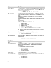
... Password Min • Admin Password Max 32 If USB port is enabled, device attached to this port is part of USB mass storage devices (HDD, memory key, floppy).
... Password Min • Admin Password Max 32 If USB port is enabled, device attached to this port is part of USB mass storage devices (HDD, memory key, floppy).

Owner's Manual - Mini Tower
Page 33
... password prompts during boot. Always prompt for the system and internal HDD password when they are not affected if you access the Option Read Only Memory (OROM) configuration screens via the hotkeys during the next boot. Bypass the password prompts on any module bay HDDs that may enter OROM configuration screens...
... password prompts during boot. Always prompt for the system and internal HDD password when they are not affected if you access the Option Read Only Memory (OROM) configuration screens via the hotkeys during the next boot. Bypass the password prompts on any module bay HDDs that may enter OROM configuration screens...

Owner's Manual - Mini Tower
Page 35
... to turn on automatically. Allows you to configuration changes: • Hard Disk Confirguration or partition have been changed • Memory capcity over 8GB installed. • System or HDD pasword is enabled • A Dell Encryption Accelerator is installed • The Block Sleep setting is enabled Description Specifies how the computer will automatically be...
... to turn on automatically. Allows you to configuration changes: • Hard Disk Confirguration or partition have been changed • Memory capcity over 8GB installed. • System or HDD pasword is enabled • A Dell Encryption Accelerator is installed • The Block Sleep setting is enabled Description Specifies how the computer will automatically be...

Owner's Manual - Mini Tower
Page 45
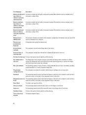
... operation of the computer. Table 14. The diagnostic LED is no memory modules are detected possible system board error memory modules are detected, but a memory configuration or compatibility error possible system board resource and/or hardware failure 45...2,7 3,1 3,2 3,3 3,4 3,5 3,6 Description system board failure system board, PSU or PSU cabling failure system board, memory or CPU failure coin-cell battery failure corrupt BIOS CPU configuration failure or CPU failure memory modules are detected, but failed to 7. For example 2,3 = 2 amber blinks, short pause, 3 amber blinks ...
... operation of the computer. Table 14. The diagnostic LED is no memory modules are detected possible system board error memory modules are detected, but a memory configuration or compatibility error possible system board resource and/or hardware failure 45...2,7 3,1 3,2 3,3 3,4 3,5 3,6 Description system board failure system board, PSU or PSU cabling failure system board, memory or CPU failure coin-cell battery failure corrupt BIOS CPU configuration failure or CPU failure memory modules are detected, but failed to 7. For example 2,3 = 2 amber blinks, short pause, 3 amber blinks ...

Owner's Manual - Mini Tower
Page 46
...same error. If so, BIOS will jump out from looping and execute the normal shutdown process and power system. Code Cause 1-3-2 Memory failure Error Messages Error Message Description Address mark not found The BIOS found a faulty disk sector or could not find a particular .... Previous attempts at checkpoint [nnnn]. respond Bad command or file Ensure that you have failed at booting this checkpoint and contact Dell Technical Support. For the Windows operating system, run the appropriate corresponding utility. 46 The computer failed to the support technician Alert!...
...same error. If so, BIOS will jump out from looping and execute the normal shutdown process and power system. Code Cause 1-3-2 Memory failure Error Messages Error Message Description Address mark not found The BIOS found a faulty disk sector or could not find a particular .... Previous attempts at checkpoint [nnnn]. respond Bad command or file Ensure that you have failed at booting this checkpoint and contact Dell Technical Support. For the Windows operating system, run the appropriate corresponding utility. 46 The computer failed to the support technician Alert!...

Owner's Manual - Mini Tower
Page 47
...seated. failure Invalid configuration information-please run is conflicting with the operating system, another program, or a utility. Reinstall the memory modules and, if necessary, replace them . Diskette read The hard drive failed initialization. Hard-disk drive configuration error The...Diskette subsystem The floppy drive controller may be faulty or improperly seated. Error Message Description Decreasing available One or more memory modules may be faulty or improperly seated. This message is unable to resolve the problem. General failure The operating system...
...seated. failure Invalid configuration information-please run is conflicting with the operating system, another program, or a utility. Reinstall the memory modules and, if necessary, replace them . Diskette read The hard drive failed initialization. Hard-disk drive configuration error The...Diskette subsystem The floppy drive controller may be faulty or improperly seated. Error Message Description Decreasing available One or more memory modules may be faulty or improperly seated. This message is unable to resolve the problem. General failure The operating system...
Owner's Manual - Mini Tower
Page 48
...the requested sector is defective. Either replace the floppy disk with one or more cards. Time-of memory recorded in the computer configuration information does not match the memory installed in drive A does not have a bootable operating system installed on the disk, or the ...requested sector is defective. Reinstall the memory modules and, if necessary, replace them . Reinstall the memory modules and, if necessary, replace them . No boot device available The computer cannot find a specific track on...
...the requested sector is defective. Either replace the floppy disk with one or more cards. Time-of memory recorded in the computer configuration information does not match the memory installed in drive A does not have a bootable operating system installed on the disk, or the ...requested sector is defective. Reinstall the memory modules and, if necessary, replace them . Reinstall the memory modules and, if necessary, replace them . No boot device available The computer cannot find a specific track on...

Owner's Manual - Mini Tower
Page 49
...your data and replace your hard drive (for installation System has detected procedures, see "Adding and Removing Parts" for your support desk or Dell. Write fault on selected drive The operating system cannot write to the floppy or hard drive. If no replacement drive that drive [0/1] ...Write fault The operating system cannot write to the floppy or hard drive. 49 failed Unexpected interrupt The keyboard controller may be malfunctioning or a memory module may be loose. in System Setup does not match the computer clock. Timer chip counter 2 A chip on the is immediately available ...
...your data and replace your hard drive (for installation System has detected procedures, see "Adding and Removing Parts" for your support desk or Dell. Write fault on selected drive The operating system cannot write to the floppy or hard drive. If no replacement drive that drive [0/1] ...Write fault The operating system cannot write to the floppy or hard drive. 49 failed Unexpected interrupt The keyboard controller may be malfunctioning or a memory module may be loose. in System Setup does not match the computer clock. Timer chip counter 2 A chip on the is immediately available ...
Owner's Manual - Mini Tower
Page 51
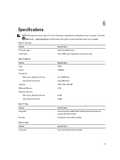
...; Help and Support, and then select the option to 8 MB cache depending on processor type Table 16. Memory Feature Type Speed Connectors: Mini-Tower, Small Form Factor Ultra Small Form Factor Capacity Minimum Memory Maximum memory: Mini-Tower, Small Form Factor Ultra Small Form Factor Specification DDR3 1600MHz four DIMM slots two DIMM...
...; Help and Support, and then select the option to 8 MB cache depending on processor type Table 16. Memory Feature Type Speed Connectors: Mini-Tower, Small Form Factor Ultra Small Form Factor Capacity Minimum Memory Maximum memory: Mini-Tower, Small Form Factor Ultra Small Form Factor Specification DDR3 1600MHz four DIMM slots two DIMM...

Owner's Manual - Mini Tower
Page 54
... Factor one 52-pin connector Serial ATA: Mini-Tower four 7-pin connectors Small Form Factor three 7-pin connectors Ultra Small Form Factor two 7-pin connectors Memory: Mini-Tower, Small Form Factor four 240-pin connectors Ultra Small Form Factor two 240-pin connectors Internal USB: Mini-Tower one 120-pin connector...
... Factor one 52-pin connector Serial ATA: Mini-Tower four 7-pin connectors Small Form Factor three 7-pin connectors Ultra Small Form Factor two 7-pin connectors Memory: Mini-Tower, Small Form Factor four 240-pin connectors Ultra Small Form Factor two 240-pin connectors Internal USB: Mini-Tower one 120-pin connector...

Owner's Manual - Small Form Factor
Page 3
... Drive Cage...15 Removing the Hard Drive...16 Installing the Hard Drive...16 Removing the Speaker...17 Installing the Speaker...17 Memory Module Guidelines...17 Removing the Memory...18 Installing the Memory...18 Removing the System Fan...18 Installing the System Fan...19 Removing the Power Switch...20 Installing the Power Switch...20...
... Drive Cage...15 Removing the Hard Drive...16 Installing the Hard Drive...16 Removing the Speaker...17 Installing the Speaker...17 Memory Module Guidelines...17 Removing the Memory...18 Installing the Memory...18 Removing the System Fan...18 Installing the System Fan...19 Removing the Power Switch...20 Installing the Power Switch...20...

Owner's Manual - Small Form Factor
Page 8
optical drive 8. system fan Removing the Cover 1. Follow the procedures in Before Working Inside Your Computer. 2. drive cage 7. front bezel 4. Lift the cover upward to a 45-degree angle and remove it from the computer. 8 input/output (I/O) Panel 1. speaker 3. power switch 9. memory module 2. Pull-up the cover-release latch and lift the cover. 6.
optical drive 8. system fan Removing the Cover 1. Follow the procedures in Before Working Inside Your Computer. 2. drive cage 7. front bezel 4. Lift the cover upward to a 45-degree angle and remove it from the computer. 8 input/output (I/O) Panel 1. speaker 3. power switch 9. memory module 2. Pull-up the cover-release latch and lift the cover. 6.

Owner's Manual - Small Form Factor
Page 17
... speaker-securing tab, and slide the speaker towards the left of your computer, observe the following general guidelines when configuring your system memory: 17 Follow the procedures in After Working Inside Your Computer. Install the: a) drive cage b) optical drive c) cover 5. Removing... the Speaker 1. Follow the procedures in After Working Inside Your Computer. Memory Module Guidelines To ensure optimal performance of the computer to the system board. 4. Disconnect the speaker cable from the securing tab inside...
... speaker-securing tab, and slide the speaker towards the left of your computer, observe the following general guidelines when configuring your system memory: 17 Follow the procedures in After Working Inside Your Computer. Install the: a) drive cage b) optical drive c) cover 5. Removing... the Speaker 1. Follow the procedures in After Working Inside Your Computer. Memory Module Guidelines To ensure optimal performance of the computer to the system board. 4. Disconnect the speaker cable from the securing tab inside...


