
Quick Reference Guide
Page 29
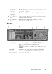
Use the microphone connector to attach headphones and most kinds of the system will be different if a riser is installed. NOTE: The back view of speakers. Quick Reference Guide 29 Insert the power cable. Can contain an optional floppy drive, second hard drive, ...
Use the microphone connector to attach headphones and most kinds of the system will be different if a riser is installed. NOTE: The back view of speakers. Quick Reference Guide 29 Insert the power cable. Can contain an optional floppy drive, second hard drive, ...
User's Guide
Page 5
... Cards 103 PCI Cards 103 Installing a PCI Card 103 Removing a PCI Card 109 Installing a PCI Card in the Riser-Card Cage 111 Removing a PCI Card From the Riser-Card Cage 114 PS/2 Serial Port Adapter 116 Installing a PS/2 Serial Port Adapter 116 Removing a PS/2 Serial Port... Adapter 118 Installing a PS/2 Serial Port Adapter in the Riser-Card Cage . 119 Removing a PS/2 Serial Port Adapter From the Riser-Card Cage 121 eSATA 123 Installing eSATA Without a Riser 123 Installing eSATA With a Riser 124 Drives 127 General Drive Installation Guidelines 127 Connecting Drive Cables 128...
... Cards 103 PCI Cards 103 Installing a PCI Card 103 Removing a PCI Card 109 Installing a PCI Card in the Riser-Card Cage 111 Removing a PCI Card From the Riser-Card Cage 114 PS/2 Serial Port Adapter 116 Installing a PS/2 Serial Port Adapter 116 Removing a PS/2 Serial Port... Adapter 118 Installing a PS/2 Serial Port Adapter in the Riser-Card Cage . 119 Removing a PS/2 Serial Port Adapter From the Riser-Card Cage 121 eSATA 123 Installing eSATA Without a Riser 123 Installing eSATA With a Riser 124 Drives 127 General Drive Installation Guidelines 127 Connecting Drive Cables 128...
User's Guide
Page 88
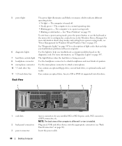
... Connectors" on page 347. See "Diagnostic Lights" on page 292. Use the lights to attach headphones and most kinds of the computer is different if a riser is turned off. • Steady green - Use the microphone connector to indicate different operating states: • No light - Insert a CD or DVD (if supported) into...
... Connectors" on page 347. See "Diagnostic Lights" on page 292. Use the lights to attach headphones and most kinds of the computer is different if a riser is turned off. • Steady green - Use the microphone connector to indicate different operating states: • No light - Insert a CD or DVD (if supported) into...
User's Guide
Page 98
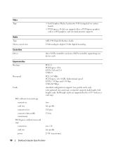
Full-height cards are supported in the 6.875-inch riser card cage. two low profile 120 pins 32 bits one device each PCI 2.3 PCI Express 1.0A SATA 1.0A and 2.0 USB 2.0 PCI: 133 MB/s PCI Express ... only; Video Type Audio Type Stereo conversion Controllers Drives Expansion Bus Bus type Bus speed Cards PCI: without riser-card cage connectors card size connector size connector data width (maximum) PCI Express: without riser-card cage connectors card size power • Intel Graphics Media Accelerator 3100 (integrated on system board) • PCI...
Full-height cards are supported in the 6.875-inch riser card cage. two low profile 120 pins 32 bits one device each PCI 2.3 PCI Express 1.0A SATA 1.0A and 2.0 USB 2.0 PCI: 133 MB/s PCI Express ... only; Video Type Audio Type Stereo conversion Controllers Drives Expansion Bus Bus type Bus speed Cards PCI: without riser-card cage connectors card size connector size connector data width (maximum) PCI Express: without riser-card cage connectors card size power • Intel Graphics Media Accelerator 3100 (integrated on system board) • PCI...
User's Guide
Page 99
... 164 pins (x16) connector data width (maximum) 16 PCI Express lanes (x16) PCI and PCI Express: with optional, full-height PCI Express riser-card cage, supporting both low-profile and full-height cards PCI connectors two card size one low-profile card and one full-height card connector... W maximum connector size 164 pins (x16) connector data width (maximum) 16 PCI Express lanes (x16) PCI only: with optional, full-height PCI riser-card cage, supporting both low-profile and full-height cards connectors three PCI card size one low-profile card and two full-height cards connector...
... 164 pins (x16) connector data width (maximum) 16 PCI Express lanes (x16) PCI and PCI Express: with optional, full-height PCI Express riser-card cage, supporting both low-profile and full-height cards PCI connectors two card size one low-profile card and one full-height card connector... W maximum connector size 164 pins (x16) connector data width (maximum) 16 PCI Express lanes (x16) PCI only: with optional, full-height PCI riser-card cage, supporting both low-profile and full-height cards connectors three PCI card size one low-profile card and two full-height cards connector...
User's Guide
Page 111
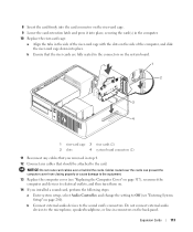
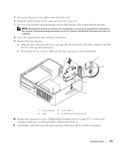
b Gently pull on the system board. 4 Remove the riser-card cage: a Check any cables that will not reach the riser-card cage once they are removed from the computer. 1 2 1 riser-card cage 2 handle Expansion Cards 111 Disconnect any cables connected to cards through the back panel openings. 12 If you ... page 90). 3 If applicable, remove the card installed in the PCI3 connector on the handle and lift the riser-card cage up and away from the computer. Installing a PCI Card in the Riser-Card Cage 1 Follow the procedures in "Before You Begin" on page 21. 2 Remove the computer cover ...
b Gently pull on the system board. 4 Remove the riser-card cage: a Check any cables that will not reach the riser-card cage once they are removed from the computer. 1 2 1 riser-card cage 2 handle Expansion Cards 111 Disconnect any cables connected to cards through the back panel openings. 12 If you ... page 90). 3 If applicable, remove the card installed in the PCI3 connector on the handle and lift the riser-card cage up and away from the computer. Installing a PCI Card in the Riser-Card Cage 1 Follow the procedures in "Before You Begin" on page 21. 2 Remove the computer cover ...
User's Guide
Page 113
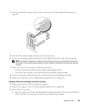
...-in connectors on the side of the computer, and slide the riser-card cage down into place, securing the card(s) in the computer. 10 Replace the riser-card cage: a Align the tabs in the connectors on the system board. 1 2 3 4 1 riser-card cage 3 riser cards (2) 2 slots 4 system board connectors (2) 11 Reconnect any cables that ... connectors. b Connect external audio devices to electrical outlets, and then turn them on page 280). 8 Insert the card firmly into the card connector on the riser-card cage. 9 Lower the card-retention latch and press it into place. b Ensure that the...
...-in connectors on the side of the computer, and slide the riser-card cage down into place, securing the card(s) in the computer. 10 Replace the riser-card cage: a Align the tabs in the connectors on the system board. 1 2 3 4 1 riser-card cage 3 riser cards (2) 2 slots 4 system board connectors (2) 11 Reconnect any cables that ... connectors. b Connect external audio devices to electrical outlets, and then turn them on page 280). 8 Insert the card firmly into the card connector on the riser-card cage. 9 Lower the card-retention latch and press it into place. b Ensure that the...
User's Guide
Page 114
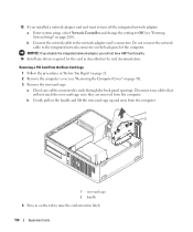
...network adapter: a Enter system setup, select Network Controller and change the setting to Off (see "Removing the Computer Cover" on page 90). 3 Remove the riser-card cage: a Check any drivers required for the card as described in "Before You Begin" on page 21. 2 Remove the computer cover (see "...Entering System Setup" on page 280). Removing a PCI Card From the Riser-Card Cage 1 Follow the procedures in the card documentation. b Gently pull on the handle and lift the riser-card cage up and away from the computer. 15 If you will not reach the...
...network adapter: a Enter system setup, select Network Controller and change the setting to Off (see "Removing the Computer Cover" on page 90). 3 Remove the riser-card cage: a Check any drivers required for the card as described in "Before You Begin" on page 21. 2 Remove the computer cover (see "...Entering System Setup" on page 280). Removing a PCI Card From the Riser-Card Cage 1 Follow the procedures in the card documentation. b Gently pull on the handle and lift the riser-card cage up and away from the computer. 15 If you will not reach the...
User's Guide
Page 115
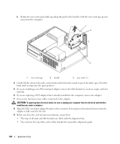
Expansion Cards 115 NOTE: Installing filler brackets over empty card-slot openings is necessary to maintain FCC certification of the riser-card cage with the card for instructions. 5 If necessary, disconnect any cables connected to the card. 6 Grasp the card by... with the slots on . 11 Uninstall the card's driver. See the documentation that the riser cards are removing the card permanently, install a filler bracket in the connectors on the system board. 1 2 3 4 1 riser-card cage 3 riser cards (2) 2 slots 4 system board connectors (2) 10 Replace the computer cover (see "...
Expansion Cards 115 NOTE: Installing filler brackets over empty card-slot openings is necessary to maintain FCC certification of the riser-card cage with the card for instructions. 5 If necessary, disconnect any cables connected to the card. 6 Grasp the card by... with the slots on . 11 Uninstall the card's driver. See the documentation that the riser cards are removing the card permanently, install a filler bracket in the connectors on the system board. 1 2 3 4 1 riser-card cage 3 riser cards (2) 2 slots 4 system board connectors (2) 10 Replace the computer cover (see "...
User's Guide
Page 119
...the card retention latch and snapping it into place. 9 Replace the computer cover (see "Replacing the Computer Cover" on page 90). 3 Remove the riser-card cage: a Check any cables connected to maintain FCC certification of your computer and maintain the airflow that cools your computer. 7 Before you are... flush with the alignment bar. • The notch in the empty card-slot opening. Installing a PS/2 Serial Port Adapter in the Riser-Card Cage 1 Follow the procedures in "Before You Begin" on page 21. 2 Remove the computer cover (see "Removing the Computer Cover" on page ...
...the card retention latch and snapping it into place. 9 Replace the computer cover (see "Replacing the Computer Cover" on page 90). 3 Remove the riser-card cage: a Check any cables connected to maintain FCC certification of your computer and maintain the airflow that cools your computer. 7 Before you are... flush with the alignment bar. • The notch in the empty card-slot opening. Installing a PS/2 Serial Port Adapter in the Riser-Card Cage 1 Follow the procedures in "Before You Begin" on page 21. 2 Remove the computer cover (see "Removing the Computer Cover" on page ...
User's Guide
Page 120
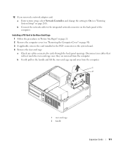
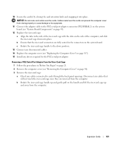
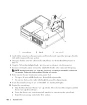
.... • The notch in the retention slot and press down firmly. b Rotate the riser-card cage handle up and gently pull on the handle to lift the riser-card cage up and away from the computer. 1 2 2 3 1 riser-card cage 2 handle 3 riser cards (2) 4 Gently lift the release tab on the card retention latch from its...
.... • The notch in the retention slot and press down firmly. b Rotate the riser-card cage handle up and gently pull on the handle to lift the riser-card cage up and away from the computer. 1 2 2 3 1 riser-card cage 2 handle 3 riser cards (2) 4 Gently lift the release tab on the card retention latch from its...
User's Guide
Page 121
... card(s) by closing properly or cause damage to the equipment. 11 Connect the adapter cable to cards through the back panel openings. c Rotate the riser-card cage handle to the down position. 13 Connect any disconnected cables. 14 Replace the computer cover (see "Replacing the Computer Cover" on page .../SERIAL2) on the system board (see "Removing the Computer Cover" on the side of the computer, and slide the riser-card cage down into place. b Ensure that will not reach the riser-card cage once they are fully seated in "Before You Begin" on page 21. 2 Remove the computer cover (see...
... card(s) by closing properly or cause damage to the equipment. 11 Connect the adapter cable to cards through the back panel openings. c Rotate the riser-card cage handle to the down position. 13 Connect any disconnected cables. 14 Replace the computer cover (see "Replacing the Computer Cover" on page .../SERIAL2) on the system board (see "Removing the Computer Cover" on the side of the computer, and slide the riser-card cage down into place. b Ensure that will not reach the riser-card cage once they are fully seated in "Before You Begin" on page 21. 2 Remove the computer cover (see...
User's Guide
Page 122
... filler brackets over empty card-slot openings is necessary to maintain FCC certification of its top corners, and ease it into place. 10 Replace the riser-card cage: a Align the tabs in the empty card-slot opening. b Ensure that : • The tops of all cards and filler brackets are removing...out of the computer. The brackets also keep dust and dirt out of your computer. 8 Before you close the card retention mechanism, ensure that the riser-card connectors are fully seated in the top of the card or filler bracket fits around the alignment guide. 9 Secure the card(s) by its connector...
... filler brackets over empty card-slot openings is necessary to maintain FCC certification of its top corners, and ease it into place. 10 Replace the riser-card cage: a Align the tabs in the empty card-slot opening. b Ensure that : • The tops of all cards and filler brackets are removing...out of the computer. The brackets also keep dust and dirt out of your computer. 8 Before you close the card retention mechanism, ensure that the riser-card connectors are fully seated in the top of the card or filler bracket fits around the alignment guide. 9 Secure the card(s) by its connector...
User's Guide
Page 123
... of your body before removal and/or replacement. Expansion Cards 123 When a device is connected, the operating system automatically recognizes the change. Installing eSATA Without a Riser 1 Remove the computer cover (see "Removing the Computer Cover" on the computer chassis. You can do so by touching an unpainted metal surface on page...
... of your body before removal and/or replacement. Expansion Cards 123 When a device is connected, the operating system automatically recognizes the change. Installing eSATA Without a Riser 1 Remove the computer cover (see "Removing the Computer Cover" on the computer chassis. You can do so by touching an unpainted metal surface on page...
User's Guide
Page 124
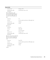
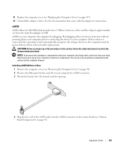
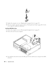
5 Replace the computer cover (see "Entering System Setup" on page 317). 6 Boot your computer. 3 Press the blue release tab to enable the eSATA drive. Installing eSATA With a Riser 1 Remove the computer cover (see "Removing the Computer Cover" on page 27). 2 Remove the riser from your computer and enter system setup (see "Replacing the Computer Cover" on page 280). Use the esata option to remove the filler panel for the card slot you are using for the eSATA connector. 124 Expansion Cards
5 Replace the computer cover (see "Entering System Setup" on page 317). 6 Boot your computer. 3 Press the blue release tab to enable the eSATA drive. Installing eSATA With a Riser 1 Remove the computer cover (see "Removing the Computer Cover" on page 27). 2 Remove the riser from your computer and enter system setup (see "Replacing the Computer Cover" on page 280). Use the esata option to remove the filler panel for the card slot you are using for the eSATA connector. 124 Expansion Cards
User's Guide
Page 126
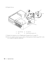
6 Replace the riser. 1 2 3 4 1 riser-card cage 3 riser cards (2) 2 slots 4 system board connectors (2) 7 Replace the computer cover (see "Replacing the Computer Cover" on page 317). 8 Boot your computer and enter system setup (see "Entering System Setup" on page 280). Use the esata option to enable the eSATA drive. 126 Expansion Cards
6 Replace the riser. 1 2 3 4 1 riser-card cage 3 riser cards (2) 2 slots 4 system board connectors (2) 7 Replace the computer cover (see "Replacing the Computer Cover" on page 317). 8 Boot your computer and enter system setup (see "Entering System Setup" on page 280). Use the esata option to enable the eSATA drive. 126 Expansion Cards


