

Quick Reference Guide
Page 8
... call status and support history, service contract, online discussions with other Dell customers Dell Support Website - Computer documentation, details on your computer, you reinstall the operating system for components, such as memory, the hard drive, and the operating system • Customer Care ..., product specifications, and white papers • Downloads - What Are You Looking For? Online discussion with technical support • Dell Technical Update Service - If you should also reinstall the DSS utility. Certified drivers, patches, and software updates • Desktop ...
... call status and support history, service contract, online discussions with other Dell customers Dell Support Website - Computer documentation, details on your computer, you reinstall the operating system for components, such as memory, the hard drive, and the operating system • Customer Care ..., product specifications, and white papers • Downloads - What Are You Looking For? Online discussion with technical support • Dell Technical Update Service - If you should also reinstall the DSS utility. Certified drivers, patches, and software updates • Desktop ...
Quick Reference Guide
Page 26
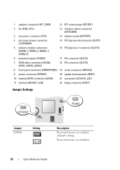
... (RTCRST) 2 fan (FAN_CPU) 13 intrusion switch connector (INTRUDER) 3 processor connector (CPU) 14 battery socket (BATTERY) 4 processor power connector (12VPOWER) 15 PCI Express x16 connector (SLOT1) 5 memory module connectors (DIMM_1, DIMM_2, DIMM_3, DIMM_4) 16 PCI Express x1 connector (SLOT4) 6 password jumper (PSWD) 17 PCI connector (SLOT2) 7 SATA drive connectors (SATA0, SATA1, SATA2...
... (RTCRST) 2 fan (FAN_CPU) 13 intrusion switch connector (INTRUDER) 3 processor connector (CPU) 14 battery socket (BATTERY) 4 processor power connector (12VPOWER) 15 PCI Express x16 connector (SLOT1) 5 memory module connectors (DIMM_1, DIMM_2, DIMM_3, DIMM_4) 16 PCI Express x1 connector (SLOT4) 6 password jumper (PSWD) 17 PCI connector (SLOT2) 7 SATA drive connectors (SATA0, SATA1, SATA2...
Quick Reference Guide
Page 47
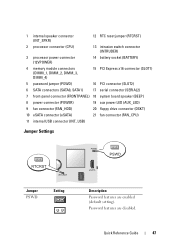
...). 1 internal speaker connector (INT_SPKR) 12 RTC reset jumper (RTCRST) 2 processor connector (CPU) 13 intrusion switch connector (INTRUDER) 3 processor power connector (12VPOWER) 14 battery socket (BATTERY) 4 memory module connectors (DIMM_1, DIMM_2, DIMM_3, DIMM_4) 15 PCI Express x16 connector (SLOT1) 5 password jumper (PSWD) 16 PCI connector (SLOT2) 6 SATA connectors (SATA0, SATA1) 17 serial...
...). 1 internal speaker connector (INT_SPKR) 12 RTC reset jumper (RTCRST) 2 processor connector (CPU) 13 intrusion switch connector (INTRUDER) 3 processor power connector (12VPOWER) 14 battery socket (BATTERY) 4 memory module connectors (DIMM_1, DIMM_2, DIMM_3, DIMM_4) 15 PCI Express x16 connector (SLOT1) 5 password jumper (PSWD) 16 PCI connector (SLOT2) 6 SATA connectors (SATA0, SATA1) 17 serial...
Quick Reference Guide
Page 57
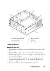
1 6 2 3 5 4 1 fan shroud/heat sink assembly 3 memory modules (2) 5 security cable slot 2 speaker (optional) 4 hard drive 6 chassis intrusion switch Cable Cover (Optional) Attaching the Cable Cover 1 Ensure that all external device cables are ...
1 6 2 3 5 4 1 fan shroud/heat sink assembly 3 memory modules (2) 5 security cable slot 2 speaker (optional) 4 hard drive 6 chassis intrusion switch Cable Cover (Optional) Attaching the Cable Cover 1 Ensure that all external device cables are ...
Quick Reference Guide
Page 60
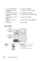
Password features are enabled (default setting). 1 fan connector (FAN_FRONT) 2 internal speaker connector (INT_SPKR) 3 system board speaker (BEEP) 4 channel B memory connector (DIMM_2) 5 channel A memory connector (DIMM_1) 6 SATA data cable connector (SATA0) 7 battery (BATT) 8 password jumper (PSWD) 9 hard drive fan connector (FAN_HDD) 10 clear CMOS jumper (RTCRST) 11 hard drive ...
Password features are enabled (default setting). 1 fan connector (FAN_FRONT) 2 internal speaker connector (INT_SPKR) 3 system board speaker (BEEP) 4 channel B memory connector (DIMM_2) 5 channel A memory connector (DIMM_1) 6 SATA data cable connector (SATA0) 7 battery (BATT) 8 password jumper (PSWD) 9 hard drive fan connector (FAN_HDD) 10 clear CMOS jumper (RTCRST) 11 hard drive ...
Quick Reference Guide
Page 62
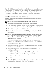
.... 4 Turn on page 63 for more information about the optional Drivers and Utilities CD. When the DELL™ logo appears, press immediately. The resulting menu displays: • Test Memory - exits Diagnostics 7 Select Test System. 8 When the Dell Diagnostics Main Menu appears, select the test you wait too long and the operating system logo...
.... 4 Turn on page 63 for more information about the optional Drivers and Utilities CD. When the DELL™ logo appears, press immediately. The resulting menu displays: • Test Memory - exits Diagnostics 7 Select Test System. 8 When the Dell Diagnostics Main Menu appears, select the test you wait too long and the operating system logo...
Quick Reference Guide
Page 64
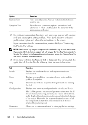
...the test and may not display the names of all the components installed on the screen. Displays your Service Tag. If you contact Dell, technical support will ask for your hardware configuration for the selected device. Your computer's Service Tag is listed in the System Info option...of each test screen. See "System Setup" in the User's Guide for more information. The Dell Diagnostics obtains configuration information for all devices attached to run a test from system setup, memory, and various internal tests, and it displays the information in the device list in the following ...
...the test and may not display the names of all the components installed on the screen. Displays your Service Tag. If you contact Dell, technical support will ask for your hardware configuration for the selected device. Your computer's Service Tag is listed in the System Info option...of each test screen. See "System Setup" in the User's Guide for more information. The Dell Diagnostics obtains configuration information for all devices attached to run a test from system setup, memory, and various internal tests, and it displays the information in the device list in the following ...
Quick Reference Guide
Page 67
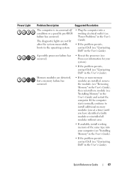
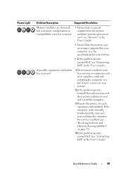
...normally, continue to the operating system. • Plug the computer into a working memory of the same type into your system). • If the problem persists, contact Dell (see "Contacting Dell" in the User's Guide) and restart the computer. Power Light Problem Description Suggested...information for your computer (see "Installing Memory" in the User's Guide). • If the problem persists, contact Dell (see "Installing Memory" in the User's Guide). Memory modules are detected, but a memory failure has occurred. • If two or more memory modules are not lit after the ...
...normally, continue to the operating system. • Plug the computer into a working memory of the same type into your system). • If the problem persists, contact Dell (see "Contacting Dell" in the User's Guide) and restart the computer. Power Light Problem Description Suggested...information for your computer (see "Installing Memory" in the User's Guide). • If the problem persists, contact Dell (see "Installing Memory" in the User's Guide). Memory modules are detected, but a memory failure has occurred. • If two or more memory modules are not lit after the ...
Quick Reference Guide
Page 68
...information for your system). • If available, install a working memory of the same type into your computer (see "Installing Memory" in the User's Guide). • If the problem persists, contact Dell (see "Contacting Dell" in the User's Guide). 68 Quick Reference Guide Reinstall all USB...without error. • If available, install working graphics card into your computer. • If the problem persists, contact Dell (see "Installing Memory" in the User's Guide). A possible floppy drive or hard drive failure has occurred. If the computer starts normally, continue ...
...information for your system). • If available, install a working memory of the same type into your computer (see "Installing Memory" in the User's Guide). • If the problem persists, contact Dell (see "Contacting Dell" in the User's Guide). 68 Quick Reference Guide Reinstall all USB...without error. • If available, install working graphics card into your computer. • If the problem persists, contact Dell (see "Installing Memory" in the User's Guide). A possible floppy drive or hard drive failure has occurred. If the computer starts normally, continue ...
Quick Reference Guide
Page 69
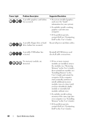
... a graphics card) and restarting the computer (see the "Cards" section for your system). • If the problem persists, contact Dell (see "Contacting Dell" in the User's Guide). Power Light Problem Description Suggested Resolution Memory modules are using is supported by your computer (see the specifications for your system). 2 If the problem persists, reinstall...
... a graphics card) and restarting the computer (see the "Cards" section for your system). • If the problem persists, contact Dell (see "Contacting Dell" in the User's Guide). Power Light Problem Description Suggested Resolution Memory modules are using is supported by your computer (see the specifications for your system). 2 If the problem persists, reinstall...
Quick Reference Guide
Page 70
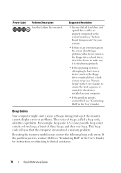
... beep. If the problem persists, contact Dell (see "Contacting Dell" in the User's Guide) for instructions on your computer. • If the problem persists, contact Dell (see "Contacting Dell" in the User's Guide). For example..., beep code 1-3-1 (one possible beep code) consists of one beep, a burst of beeps, called a beep code, identifies a problem. Power Light Problem Description Another failure has occurred. Suggested Resolution • Ensure that the computer encountered a memory problem. Reseating the memory...
... beep. If the problem persists, contact Dell (see "Contacting Dell" in the User's Guide) for instructions on your computer. • If the problem persists, contact Dell (see "Contacting Dell" in the User's Guide). For example..., beep code 1-3-1 (one possible beep code) consists of one beep, a burst of beeps, called a beep code, identifies a problem. Power Light Problem Description Another failure has occurred. Suggested Resolution • Ensure that the computer encountered a memory problem. Reseating the memory...
Quick Reference Guide
Page 71
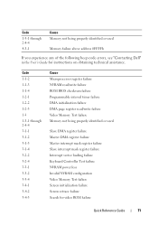
... code errors, see "Contacting Dell" in the User's Guide for video ROM failure Quick Reference Guide 71 Code 1-3-1 through 2-4-4 3-1-1 3-1-2 3-1-3 3-1-4 3-2-2 3-2-4 3-3-1 3-3-2 3-3-4 3-4-1 3-4-2 3-4-3 Cause Microprocessor register failure NVRAM read/write failure ROM BIOS checksum failure Programmable interval timer failure DMA initialization failure DMA page register read/write failure Video Memory Test failure Memory not being properly identified...
... code errors, see "Contacting Dell" in the User's Guide for video ROM failure Quick Reference Guide 71 Code 1-3-1 through 2-4-4 3-1-1 3-1-2 3-1-3 3-1-4 3-2-2 3-2-4 3-3-1 3-3-2 3-3-4 3-4-1 3-4-2 3-4-3 Cause Microprocessor register failure NVRAM read/write failure ROM BIOS checksum failure Programmable interval timer failure DMA initialization failure DMA page register read/write failure Video Memory Test failure Memory not being properly identified...
Quick Reference Guide
Page 72
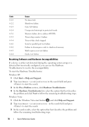
...Code 4-2-1 4-2-2 4-2-3 4-2-4 4-3-1 4-3-3 4-3-4 4-4-1 4-4-2 4-4-3 4-4-4 Cause No timer tick Shutdown failure Gate A20 failure Unexpected interrupt in protected mode Memory failure above address 0FFFFh Timer-chip counter 2 failure Time-of-day clock stopped Serial or parallel port test failure Failure to decompress code to shadowed... memory Math-coprocessor test failure Cache test failure Resolving Software and Hardware Incompatibilities If a device is either not detected during ...
...Code 4-2-1 4-2-2 4-2-3 4-2-4 4-3-1 4-3-3 4-3-4 4-4-1 4-4-2 4-4-3 4-4-4 Cause No timer tick Shutdown failure Gate A20 failure Unexpected interrupt in protected mode Memory failure above address 0FFFFh Timer-chip counter 2 failure Time-of-day clock stopped Serial or parallel port test failure Failure to decompress code to shadowed... memory Math-coprocessor test failure Cache test failure Resolving Software and Hardware Incompatibilities If a device is either not detected during ...
User's Guide
Page 11
... Sequence 287 Option Settings 287 Changing Boot Sequence for the Current Boot 287 Changing Boot Sequence for Future Boots 288 Booting to a USB Device 288 Memory Key 288 Floppy Drive 289 Jumper Settings 289 Clearing Forgotten Passwords 290 Clearing CMOS Settings 291 Hyperthreading and Multi-Core Technology 292 Power Management for...
... Sequence 287 Option Settings 287 Changing Boot Sequence for the Current Boot 287 Changing Boot Sequence for Future Boots 288 Booting to a USB Device 288 Memory Key 288 Floppy Drive 289 Jumper Settings 289 Clearing Forgotten Passwords 290 Clearing CMOS Settings 291 Hyperthreading and Multi-Core Technology 292 Power Management for...
User's Guide
Page 12
... Screws 311 Replacing the System Board: Mini Tower, Desktop, Small Form Factor, and Ultra Small Form Factor Computers 311 12 Memory DDR2 Memory Overview 313 Addressing Memory Configurations 314 Installing Memory 314 Removing Memory 316 13 Replacing the Computer Cover Mini-Tower, Desktop, and Small Form Factor Computers 317 Ultra Small Form Factor Computers 317...
... Screws 311 Replacing the System Board: Mini Tower, Desktop, Small Form Factor, and Ultra Small Form Factor Computers 311 12 Memory DDR2 Memory Overview 313 Addressing Memory Configurations 314 Installing Memory 314 Removing Memory 316 13 Replacing the Computer Cover Mini-Tower, Desktop, and Small Form Factor Computers 317 Ultra Small Form Factor Computers 317...
User's Guide
Page 14
... 337 A program is designed for an earlier Windows operating system 337 A solid blue screen appears 337 Other software problems 337 Memory Problems 338 Mouse Problems 338 Network Problems 339 Power Problems 339 Troubleshooting Power Problems 339 Power Supply Self-Test 340 Printer Problems ... 347 Beep Codes 350 System Messages 351 Dell Diagnostics 353 When to Use the Dell Diagnostics 353 Starting the Dell Diagnostics From Your Hard Drive . . . . . 353 Starting the Dell Diagnostics From the Drivers and Utilities CD (Optional 354 Dell Diagnostics Main Menu 355 Drivers 356 14 ...
... 337 A program is designed for an earlier Windows operating system 337 A solid blue screen appears 337 Other software problems 337 Memory Problems 338 Mouse Problems 338 Network Problems 339 Power Problems 339 Troubleshooting Power Problems 339 Power Supply Self-Test 340 Printer Problems ... 347 Beep Codes 350 System Messages 351 Dell Diagnostics 353 When to Use the Dell Diagnostics 353 Starting the Dell Diagnostics From Your Hard Drive . . . . . 353 Starting the Dell Diagnostics From the Drivers and Utilities CD (Optional 354 Dell Diagnostics Main Menu 355 Drivers 356 14 ...
User's Guide
Page 19
... configuration. • How to use Windows XP • How to work with other Dell customers • Upgrades - for correct operation of software and hardware updates for components, such as memory, the hard drive, and the operating system • Customer Care - The NOTE: The... support.dell.com user interface may vary software automatically detects your computer and depending on my computer ...
... configuration. • How to use Windows XP • How to work with other Dell customers • Upgrades - for correct operation of software and hardware updates for components, such as memory, the hard drive, and the operating system • Customer Care - The NOTE: The... support.dell.com user interface may vary software automatically detects your computer and depending on my computer ...

User's Guide
Page 32
System Board Components 1 2 3 22 21 20 19 18 17 16 15 4 5 6 7 8 14 13 12 1 speaker connector (INT_SPKR) 2 fan (FAN_CPU) 3 processor connector (CPU) 4 processor power connector (12VPOWER) 5 memory module connectors (DIMM_1, DIMM_2, DIMM_3, DIMM_4) 11 10 9 12 RTC reset jumper (RTCRST) 13 intrusion switch connector (INTRUDER) 14 battery socket (BATTERY) 15 PCI Express x16 connector (SLOT1) 16 PCI Express x1 connector (SLOT4) 32 Mini Tower Computer
System Board Components 1 2 3 22 21 20 19 18 17 16 15 4 5 6 7 8 14 13 12 1 speaker connector (INT_SPKR) 2 fan (FAN_CPU) 3 processor connector (CPU) 4 processor power connector (12VPOWER) 5 memory module connectors (DIMM_1, DIMM_2, DIMM_3, DIMM_4) 11 10 9 12 RTC reset jumper (RTCRST) 13 intrusion switch connector (INTRUDER) 14 battery socket (BATTERY) 15 PCI Express x16 connector (SLOT1) 16 PCI Express x1 connector (SLOT4) 32 Mini Tower Computer

User's Guide
Page 35
... by DMTF Capable of 10/100/1000 communication iAMT 3.0 Mini Tower Specifications 35 Mini Tower Computer Specifications Microprocessor Microprocessor type Internal cache Memory Type Memory connectors Memory modules supported Minimum memory Maximum memory BIOS address Computer Information Chipset Data bus width Address bus width DMA channels Interrupt levels BIOS chip (NVRAM) NIC The following are...
... by DMTF Capable of 10/100/1000 communication iAMT 3.0 Mini Tower Specifications 35 Mini Tower Computer Specifications Microprocessor Microprocessor type Internal cache Memory Type Memory connectors Memory modules supported Minimum memory Maximum memory BIOS address Computer Information Chipset Data bus width Address bus width DMA channels Interrupt levels BIOS chip (NVRAM) NIC The following are...
User's Guide
Page 97
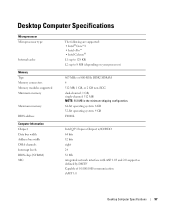
... 800-MHz DDR2 SDRAM 4 512 MB, 1 GB, or 2 GB non-ECC dual-channel: 1 GB; Desktop Computer Specifications Microprocessor Microprocessor type Internal cache Memory Type Memory connectors Memory modules supported Minimum memory Maximum memory BIOS address Computer Information Chipset Data bus width Address bus width DMA channels Interrupt levels BIOS chip (NVRAM) NIC The following are...
... 800-MHz DDR2 SDRAM 4 512 MB, 1 GB, or 2 GB non-ECC dual-channel: 1 GB; Desktop Computer Specifications Microprocessor Microprocessor type Internal cache Memory Type Memory connectors Memory modules supported Minimum memory Maximum memory BIOS address Computer Information Chipset Data bus width Address bus width DMA channels Interrupt levels BIOS chip (NVRAM) NIC The following are...


