
Quick Reference Guide
Page 3
... Views 16 Removing the Computer Cover 22 Inside Your Computer 24 System Board Components 25 Jumper Settings 26 Desktop Computer 27 System Views 27 Removing the Computer Cover 32 Inside Your Computer 33 System Board Components 35 Jumper Settings 36 Small Form Factor Computer 37 System Views 37 Removing the Computer Cover 43 Contents 3
... Views 16 Removing the Computer Cover 22 Inside Your Computer 24 System Board Components 25 Jumper Settings 26 Desktop Computer 27 System Views 27 Removing the Computer Cover 32 Inside Your Computer 33 System Board Components 35 Jumper Settings 36 Small Form Factor Computer 37 System Views 37 Removing the Computer Cover 43 Contents 3
Quick Reference Guide
Page 15
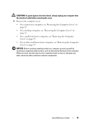
... a mini tower computer, see "Removing the Computer Cover" on page 22. • For a desktop computer, see "Removing the Computer Cover" on page 32. • For a small form factor computer, see "Removing the Computer Cover" on page 43. • For an ultra small form factor computer, see "Removing the Computer Cover" on page 55. Quick Reference Guide 15
... a mini tower computer, see "Removing the Computer Cover" on page 22. • For a desktop computer, see "Removing the Computer Cover" on page 32. • For a small form factor computer, see "Removing the Computer Cover" on page 43. • For an ultra small form factor computer, see "Removing the Computer Cover" on page 55. Quick Reference Guide 15
User's Guide
Page 12
... the System Board Removing the System Board: Mini Tower, Desktop, Small Form Factor, and Ultra Small Form Factor Computers 307 Mini Tower System Board Screws 308 Desktop System Board Screws 309 Small Form Factor System Board Screws 310 Ultra Small Form Factor System Board Screws 311 Replacing the System Board: Mini Tower, Desktop, Small Form Factor, and Ultra Small Form Factor Computers 311 12 Memory DDR2 Memory Overview 313 Addressing Memory...
... the System Board Removing the System Board: Mini Tower, Desktop, Small Form Factor, and Ultra Small Form Factor Computers 307 Mini Tower System Board Screws 308 Desktop System Board Screws 309 Small Form Factor System Board Screws 310 Ultra Small Form Factor System Board Screws 311 Replacing the System Board: Mini Tower, Desktop, Small Form Factor, and Ultra Small Form Factor Computers 311 12 Memory DDR2 Memory Overview 313 Addressing Memory...
User's Guide
Page 22
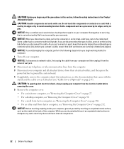
..."Removing the Computer Cover" on page 27. • For a desktop computer, see "Removing the Computer Cover" on page 90. • For a small form factor computer, see "Removing the Computer Cover" on page 168. • For an ultra small form factor computer, see "Cable Cover (Optional)" on your computer and all ... your computer. As you pull connectors apart, keep them evenly aligned to dissipate any static electricity that is not authorized by Dell is not covered by its pins. While you work, periodically touch an unpainted metal surface to avoid bending any connector pins....
..."Removing the Computer Cover" on page 27. • For a desktop computer, see "Removing the Computer Cover" on page 90. • For a small form factor computer, see "Removing the Computer Cover" on page 168. • For an ultra small form factor computer, see "Cable Cover (Optional)" on your computer and all ... your computer. As you pull connectors apart, keep them evenly aligned to dissipate any static electricity that is not authorized by Dell is not covered by its pins. While you work, periodically touch an unpainted metal surface to avoid bending any connector pins....
User's Guide
Page 29
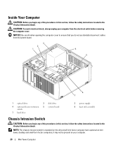
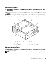
... electrical shock, always unplug your computer. 29 Mini Tower Computer it may not be present on mini tower, desktop and small form factor computers; Inside Your Computer CAUTION: Before you begin any of the procedures in this section, follow the safety ...instructions located in the Product Information Guide. NOTE: The chassis intrusion switch is standard on the ultra small form factor computer but is optional on your computer from the system board. 3 2 1 4 5 6 7 1 optical drive 4 optional chassis-intrusion switch 7...
... electrical shock, always unplug your computer. 29 Mini Tower Computer it may not be present on mini tower, desktop and small form factor computers; Inside Your Computer CAUTION: Before you begin any of the procedures in this section, follow the safety ...instructions located in the Product Information Guide. NOTE: The chassis intrusion switch is standard on the ultra small form factor computer but is optional on your computer from the system board. 3 2 1 4 5 6 7 1 optical drive 4 optional chassis-intrusion switch 7...
User's Guide
Page 92
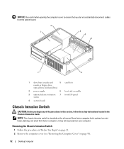
..." on your computer. Removing the Chassis Intrusion Switch 1 Follow the procedures in the Product Information Guide. it may not be present on page 90). 92 Desktop Computer NOTE: The chassis intrusion switch is standard on the ultra small form factor computer but is optional on mini tower, desktop, and small form factor computers;
..." on your computer. Removing the Chassis Intrusion Switch 1 Follow the procedures in the Product Information Guide. it may not be present on page 90). 92 Desktop Computer NOTE: The chassis intrusion switch is standard on the ultra small form factor computer but is optional on mini tower, desktop, and small form factor computers;
User's Guide
Page 170
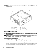
...). 4 Disconnect the chassis intrusion switch cable from the system board by using two fingers to disconnect the cable connector. 170 Small Form Factor Computer it may not be present on mini tower, desktop, and small form factor computers; Removing the Chassis Intrusion Switch 1 Follow the procedures in the Product Information Guide. NOTE: The chassis intrusion switch is...
...). 4 Disconnect the chassis intrusion switch cable from the system board by using two fingers to disconnect the cable connector. 170 Small Form Factor Computer it may not be present on mini tower, desktop, and small form factor computers; Removing the Chassis Intrusion Switch 1 Follow the procedures in the Product Information Guide. NOTE: The chassis intrusion switch is...
User's Guide
Page 171
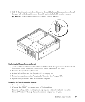
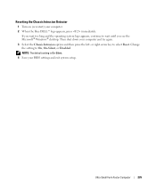
... a Hard Drive" on page 199). 4 Replace the computer cover (see the Microsoft® Windows® desktop. Then shut down through the square hole in the bracket to the computer. Small Form Factor Computer 171 5 Slide the chassis intrusion switch out of the slot. Resetting the Chassis Intrusion Detector 1 Turn ... then slide the chassis intrusion switch into its slot in the metal bracket, and then push it down your computer. 2 When the blue DELL™ logo appears, press immediately. NOTE: You may feel a slight resistance as you slide the switch out of its slot until you ...
... a Hard Drive" on page 199). 4 Replace the computer cover (see the Microsoft® Windows® desktop. Then shut down through the square hole in the bracket to the computer. Small Form Factor Computer 171 5 Slide the chassis intrusion switch out of the slot. Resetting the Chassis Intrusion Detector 1 Turn ... then slide the chassis intrusion switch into its slot in the metal bracket, and then push it down your computer. 2 When the blue DELL™ logo appears, press immediately. NOTE: You may feel a slight resistance as you slide the switch out of its slot until you ...
User's Guide
Page 233
...touch any of your computer's electronic components. NOTICE: To prevent static damage to components inside your computer. Ultra Small Form Factor Computer 233 NOTE: The chassis intrusion switch is standard on the ultra small form factor computer but is optional on the computer chassis. 1 2 6 3 5 4 1 fan shroud/heat sink... in the Product Information Guide. You can do so by touching an unpainted metal surface on mini tower, desktop and small form factor computers; Inside Your Computer CAUTION: Before you begin any of the procedures in this section, follow the safety...
...touch any of your computer's electronic components. NOTICE: To prevent static damage to components inside your computer. Ultra Small Form Factor Computer 233 NOTE: The chassis intrusion switch is standard on the ultra small form factor computer but is optional on the computer chassis. 1 2 6 3 5 4 1 fan shroud/heat sink... in the Product Information Guide. You can do so by touching an unpainted metal surface on mini tower, desktop and small form factor computers; Inside Your Computer CAUTION: Before you begin any of the procedures in this section, follow the safety...
User's Guide
Page 235
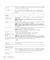
Change the setting to wait until you see the Microsoft® Windows® desktop. Then shut down your BIOS settings and exit system setup. Ultra Small Form Factor Computer 235 NOTE: The default setting is On-Silent. 4 Save your computer and try again. 3 Select the Chassis Intrusion option and then press the left- ..., On-Silent, or Disabled. or right-arrow key to select Reset. Resetting the Chassis Intrusion Detector 1 Turn on (or restart) your computer. 2 When the blue DELL™ logo appears, press immediately.
Change the setting to wait until you see the Microsoft® Windows® desktop. Then shut down your BIOS settings and exit system setup. Ultra Small Form Factor Computer 235 NOTE: The default setting is On-Silent. 4 Save your computer and try again. 3 Select the Chassis Intrusion option and then press the left- ..., On-Silent, or Disabled. or right-arrow key to select Reset. Resetting the Chassis Intrusion Detector 1 Turn on (or restart) your computer. 2 When the blue DELL™ logo appears, press immediately.
User's Guide
Page 282
... and disables the drives attached to On. form factor and ultra small Options for mini-tower and • RAID On (SATA is detected on the ultra small form factor computer. SATA Operation Options for Mini Tower and Desktop: (RAID • RAID Autodetect/AHCI (...RAID if signed drives, otherwise AHCI) Autodetect/AHCI • RAID Autodetect/ATA (RAID if signed drives, otherwise ATA) default for Small Form Factor and Ultra Small Form Factor: form factor) •...
... and disables the drives attached to On. form factor and ultra small Options for mini-tower and • RAID On (SATA is detected on the ultra small form factor computer. SATA Operation Options for Mini Tower and Desktop: (RAID • RAID Autodetect/AHCI (...RAID if signed drives, otherwise AHCI) Autodetect/AHCI • RAID Autodetect/ATA (RAID if signed drives, otherwise ATA) default for Small Form Factor and Ultra Small Form Factor: form factor) •...
User's Guide
Page 289
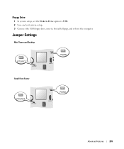
Floppy Drive 1 In system setup, set the Diskette Drive option to USB. 2 Save and exit system setup. 3 Connect the USB floppy drive, insert a bootable floppy, and re-boot the computer. Jumper Settings Mini Tower and Desktop Small Form Factor Advanced Features 289
Floppy Drive 1 In system setup, set the Diskette Drive option to USB. 2 Save and exit system setup. 3 Connect the USB floppy drive, insert a bootable floppy, and re-boot the computer. Jumper Settings Mini Tower and Desktop Small Form Factor Advanced Features 289
User's Guide
Page 307
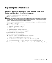
...: see "Mini Tower System Board Screws" on page 308 • Desktop: see "Desktop System Board Screws" on page 309 • Small form factor: see "Small Form Factor System Board Screws" on page 310 • Ultra small form factor: see "Ultra Small Form Factor System Board Screws" on page 21. 2 Remove the computer cover. ... and then lift the board up and away. Replacing the System Board Removing the System Board: Mini Tower, Desktop, Small Form Factor, and Ultra Small Form Factor Computers 1 Follow the procedures in "Before You Begin" on page 311 7 Slide the system board assembly toward the...
...: see "Mini Tower System Board Screws" on page 308 • Desktop: see "Desktop System Board Screws" on page 309 • Small form factor: see "Small Form Factor System Board Screws" on page 310 • Ultra small form factor: see "Ultra Small Form Factor System Board Screws" on page 21. 2 Remove the computer cover. ... and then lift the board up and away. Replacing the System Board Removing the System Board: Mini Tower, Desktop, Small Form Factor, and Ultra Small Form Factor Computers 1 Follow the procedures in "Before You Begin" on page 311 7 Slide the system board assembly toward the...
User's Guide
Page 311
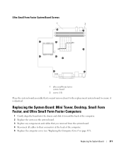
Replacing the System Board: Mini Tower, Desktop, Small Form Factor, and Ultra Small Form Factor Computers 1 Gently align the board into the chassis and slide it is identical. Replacing the System Board 311 Ultra Small Form Factor System Board Screws 1 2 1 ultra small form factor system board 2 screws (10) Place the system board assembly that you just removed next to the replacement system board to...
Replacing the System Board: Mini Tower, Desktop, Small Form Factor, and Ultra Small Form Factor Computers 1 Gently align the board into the chassis and slide it is identical. Replacing the System Board 311 Ultra Small Form Factor System Board Screws 1 2 1 ultra small form factor system board 2 screws (10) Place the system board assembly that you just removed next to the replacement system board to...
User's Guide
Page 317
...: a Align the bottom of the cover with the stand. 5 Connect your computer's electronic components. Replacing the Computer Cover Mini-Tower, Desktop, and Small Form Factor Computers CAUTION: Before you begin any of the procedures in this section, follow the safety instructions in the Product Information Guide. d Ensure ... the cable into place by touching an unpainted metal surface on the screen at the next computer startup: ALERT! Ultra Small Form Factor Computers CAUTION: Before you so that came with the hinge tabs located along the bottom edge of the way. Replacing the Computer ...
...: a Align the bottom of the cover with the stand. 5 Connect your computer's electronic components. Replacing the Computer Cover Mini-Tower, Desktop, and Small Form Factor Computers CAUTION: Before you begin any of the procedures in this section, follow the safety instructions in the Product Information Guide. d Ensure ... the cable into place by touching an unpainted metal surface on the screen at the next computer startup: ALERT! Ultra Small Form Factor Computers CAUTION: Before you so that came with the hinge tabs located along the bottom edge of the way. Replacing the Computer ...
User's Guide
Page 319
... a mini tower computer, see "Mini Tower Computer Specifications" on page 35. • For a desktop computer, see "Desktop Computer Specifications" on page 97. • For a small form factor computer, see "Small Form Factor Computer Specifications" on page 175. • For an ultra small form factor computer, see "Ultra Small Form Factor Computer Specifications" on page 241. • Leave a 10.2-centimeter (4-inch) minimum clearance on your...
... a mini tower computer, see "Mini Tower Computer Specifications" on page 35. • For a desktop computer, see "Desktop Computer Specifications" on page 97. • For a small form factor computer, see "Small Form Factor Computer Specifications" on page 175. • For an ultra small form factor computer, see "Ultra Small Form Factor Computer Specifications" on page 241. • Leave a 10.2-centimeter (4-inch) minimum clearance on your...
User's Guide
Page 340
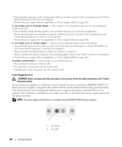
... page 313). • Remove and then reinstall any of the procedures in this section, follow the safety instructions in isolation. I F T H E P O W E R L I G H T I S B L I N K I S S T E A D Y A M B E R - I F T H E P O W E R L I G H T I N G A M B E R - If your mini tower, desktop, or small form factor computer has been certified for ENERGY STAR® 4.0, then your power supply is set to match the AC power at your location (if applicable). •...
... page 313). • Remove and then reinstall any of the procedures in this section, follow the safety instructions in isolation. I F T H E P O W E R L I G H T I S B L I N K I S S T E A D Y A M B E R - I F T H E P O W E R L I G H T I N G A M B E R - If your mini tower, desktop, or small form factor computer has been certified for ENERGY STAR® 4.0, then your power supply is set to match the AC power at your location (if applicable). •...
User's Guide
Page 341
... your computer: • For the mini tower, see "Power Supply" on page 79 • For the desktop, see "Power Supply" on page 155 • For the small form factor, see "Power Supply" on page 219 3 Connect your computer off and disconnect the computer from the electrical outlet... test LED illuminates, the power supply is listed, right-click the printer icon. 3 Click Properties→ Ports. Replace the defective device/part or contact Dell (see "Contacting Dell" on page 370). - TE ST T H E E L E CT R I O N - For a parallel printer, ensure that the electrical outlet is working ...
... your computer: • For the mini tower, see "Power Supply" on page 79 • For the desktop, see "Power Supply" on page 155 • For the small form factor, see "Power Supply" on page 219 3 Connect your computer off and disconnect the computer from the electrical outlet... test LED illuminates, the power supply is listed, right-click the printer icon. 3 Click Properties→ Ports. Replace the defective device/part or contact Dell (see "Contacting Dell" on page 370). - TE ST T H E E L E CT R I O N - For a parallel printer, ensure that the electrical outlet is working ...


