
User's Guide
Page 27
3 2 1 4 5 1 optical drive 4 chassis intrusion switch (optional) 7 hard drive 2 floppy drive 5 system board 6 7 3 power supply 6 heat sink assembly Mini Tower Computer 27
3 2 1 4 5 1 optical drive 4 chassis intrusion switch (optional) 7 hard drive 2 floppy drive 5 system board 6 7 3 power supply 6 heat sink assembly Mini Tower Computer 27
User's Guide
Page 35
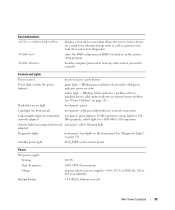
... "Diagnostic Lights" on integrated network adapter) rear panel - Standby power light AUX_PWR on the system board Power DC power supply: Wattage Heat dissipation Voltage Backup battery 305 W 1040.7 BTU/hr maximum manual selection power supplies-90 to 135 V at 50/60 Hz 3-V CR2032 lithium coin cell Mini Tower Computer 35 green light for 100Mb operation; solid green light...
... "Diagnostic Lights" on integrated network adapter) rear panel - Standby power light AUX_PWR on the system board Power DC power supply: Wattage Heat dissipation Voltage Backup battery 305 W 1040.7 BTU/hr maximum manual selection power supplies-90 to 135 V at 50/60 Hz 3-V CR2032 lithium coin cell Mini Tower Computer 35 green light for 100Mb operation; solid green light...
User's Guide
Page 89
... You must route these cables properly when you remove them from being pinched or crimped. 3 Remove the four screws that attach the power supply to components inside your computer, discharge static electricity from the system board and the drives. NOTICE: To prevent static damage to the back... metal surface on the computer chassis. 1 Follow the procedures in "Before You Begin" on the floor of the computer chassis. Power Supply Replacing the Power Supply CAUTION: Before you touch any of your body before you begin any of the procedures in this section, follow the safety instructions ...
... You must route these cables properly when you remove them from being pinched or crimped. 3 Remove the four screws that attach the power supply to components inside your computer, discharge static electricity from the system board and the drives. NOTICE: To prevent static damage to the back... metal surface on the computer chassis. 1 Follow the procedures in "Before You Begin" on the floor of the computer chassis. Power Supply Replacing the Power Supply CAUTION: Before you touch any of your body before you begin any of the procedures in this section, follow the safety instructions ...

User's Guide
Page 90
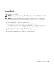
Mini Tower Computer 90 1 2 3 4 1 release button 4 AC power connector 2 power supply 3 screws (4) 5 Slide the power supply toward the front of the computer by approximately 1 inch. 6 Lift the power supply up and out of the computer. 7 Slide the replacement power supply into place. 8 Replace the screws that secure the power supply to the back of the computer chassis.
Mini Tower Computer 90 1 2 3 4 1 release button 4 AC power connector 2 power supply 3 screws (4) 5 Slide the power supply toward the front of the computer by approximately 1 inch. 6 Lift the power supply up and out of the computer. 7 Slide the replacement power supply into place. 8 Replace the screws that secure the power supply to the back of the computer chassis.


