Quick Reference Guide
Page 15
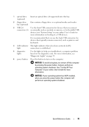
...Your Computer" in your online User's Guide for more information on booting to help you use the back USB connectors for devices that typically remain connected, such as joysticks or cameras, or for bootable USB devices (see "Diagnostic Lights" on the diagnostic code. It is...the computer will perform an operating system shutdown. Instead, perform an operating system shutdown. Quick Reference Guide 15 bay (optional) 3 USB 2.0 Use the front USB connectors for devices that you troubleshoot a computer problem based on page 55. 6 power button Press this bay. (optional) 2 floppy...
...Your Computer" in your online User's Guide for more information on booting to help you use the back USB connectors for devices that typically remain connected, such as joysticks or cameras, or for bootable USB devices (see "Diagnostic Lights" on the diagnostic code. It is...the computer will perform an operating system shutdown. Instead, perform an operating system shutdown. Quick Reference Guide 15 bay (optional) 3 USB 2.0 Use the front USB connectors for devices that you troubleshoot a computer problem based on page 55. 6 power button Press this bay. (optional) 2 floppy...
Quick Reference Guide
Page 21
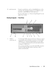
.... Front View 1 2 3 11 10 1 USB 2.0 connectors (2) 9 876 5 4 Use the front USB connectors for devices that you connect occasionally, such as a handheld device, to a USB device). Desktop Computer - For more information about booting to the serial port. Quick Reference Guide 21 It... is recommended that you use the back USB connectors for serial connector 2. 9 serial connector Connect a ...
.... Front View 1 2 3 11 10 1 USB 2.0 connectors (2) 9 876 5 4 Use the front USB connectors for devices that you connect occasionally, such as a handheld device, to a USB device). Desktop Computer - For more information about booting to the serial port. Quick Reference Guide 21 It... is recommended that you use the back USB connectors for serial connector 2. 9 serial connector Connect a ...
Quick Reference Guide
Page 27
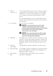
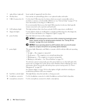
... in your operating system has ACPI enabled, when you press the power button the computer will perform an operating system shutdown. 3 Dell badge This badge can also rotate the badge using the slot provided near the bottom of the badge, press firmly, and turn off... the computer by pressing the power button. NOTICE: If your online User's Guide for instructions about booting to a USB device). 1 USB 2.0 connectors (2) Use the front USB connectors for devices that a LAN (local area network) connection is being accessed. 5 diagnostic lights Use the lights to help...
... in your operating system has ACPI enabled, when you press the power button the computer will perform an operating system shutdown. 3 Dell badge This badge can also rotate the badge using the slot provided near the bottom of the badge, press firmly, and turn off... the computer by pressing the power button. NOTICE: If your online User's Guide for instructions about booting to a USB device). 1 USB 2.0 connectors (2) Use the front USB connectors for devices that a LAN (local area network) connection is being accessed. 5 diagnostic lights Use the lights to help...
User's Guide
Page 6
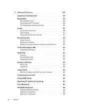
6 Advanced Features 249 LegacySelect Technology Control 249 Manageability 249 Alert Standard Format 249 Dell OpenManage™ IT Assistant 250 Dell OpenManage Client Instrumentation 250 Security 250 Chassis Intrusion Detection 250 Option Settings 251 Padlock Ring and ...Trusted Platform Module (TPM 255 Enabling the TPM Feature 255 System Setup 257 Overview 257 Entering System Setup 257 System Setup Options 258 Booting to a USB Device 264 Memory Key 264 Floppy Drive 264 Jumper Settings 265 Mini Tower, Desktop, and Small Form Factor Computers 265 Clearing Forgotten Passwords...
6 Advanced Features 249 LegacySelect Technology Control 249 Manageability 249 Alert Standard Format 249 Dell OpenManage™ IT Assistant 250 Dell OpenManage Client Instrumentation 250 Security 250 Chassis Intrusion Detection 250 Option Settings 251 Padlock Ring and ...Trusted Platform Module (TPM 255 Enabling the TPM Feature 255 System Setup 257 Overview 257 Entering System Setup 257 System Setup Options 258 Booting to a USB Device 264 Memory Key 264 Floppy Drive 264 Jumper Settings 265 Mini Tower, Desktop, and Small Form Factor Computers 265 Clearing Forgotten Passwords...
User's Guide
Page 22
...6 power button 7 power light 8 hard-drive activity light 9 headphone connector 10 microphone connector Insert media (if supported) into this button to a USB device). Use the front USB connectors for devices that you use the keyboard or the mouse if it is in a power-saving mode. • Blinking or solid amber... - To exit from a power-saving mode, see "System Setup" on booting to turn off . • Steady green - Use the lights to ...
...6 power button 7 power light 8 hard-drive activity light 9 headphone connector 10 microphone connector Insert media (if supported) into this button to a USB device). Use the front USB connectors for devices that you use the keyboard or the mouse if it is in a power-saving mode. • Blinking or solid amber... - To exit from a power-saving mode, see "System Setup" on booting to turn off . • Steady green - Use the lights to ...

User's Guide
Page 97
...cameras, or for bootable USB devices (see "System Setup" on page 257 for devices that typically remain connected, such as printers and keyboards. 2 LAN indicator light This light indicates that you press the power button the computer will perform an operating system shutdown. 4 Dell badge This badge can ...also rotate the badge using the slot provided near the bottom of the badge. See "Turning Off Your Computer" on page 19 for more information about booting to turn on the computer.
...cameras, or for bootable USB devices (see "System Setup" on page 257 for devices that typically remain connected, such as printers and keyboards. 2 LAN indicator light This light indicates that you press the power button the computer will perform an operating system shutdown. 4 Dell badge This badge can ...also rotate the badge using the slot provided near the bottom of the badge. See "Turning Off Your Computer" on page 19 for more information about booting to turn on the computer.

User's Guide
Page 108
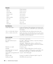
...the Windows Security window; two front-panel connectors for headphones and microphone three 7-pin connectors 38-pin connector 24-pin connector for a single boot (during system start -up only) as well as options to enter a device for optional second serial port card 5-pin connector two 124-... switch Speaker Memory modules Power 12V Power Battery Front panel two front-panel and five back-panel USB 2.0-compliant connectors two connectors for line-in the system setup program displays a boot device menu that allows the user to run hard-drive and system diagnostics Controls and Lights Power...
...the Windows Security window; two front-panel connectors for headphones and microphone three 7-pin connectors 38-pin connector 24-pin connector for a single boot (during system start -up only) as well as options to enter a device for optional second serial port card 5-pin connector two 124-... switch Speaker Memory modules Power 12V Power Battery Front panel two front-panel and five back-panel USB 2.0-compliant connectors two connectors for line-in the system setup program displays a boot device menu that allows the user to run hard-drive and system diagnostics Controls and Lights Power...

User's Guide
Page 185
... View 1 2 3 5 4 5 6 11 10 98 7 1 USB 2.0 connectors (2) Use the front USB connectors for devices that typically remain connected, such as joysticks or cameras, or for bootable USB devices (see "System Setup" on page 257 for more information about booting to turn on page 19 for more information. NOTICE: If..., do not turn the badge. It is recommended that you use the back USB connectors for devices that you press the power button the computer will perform an operating system shutdown. 3 Dell badge This badge can also rotate the badge using the slot provided near the ...
... View 1 2 3 5 4 5 6 11 10 98 7 1 USB 2.0 connectors (2) Use the front USB connectors for devices that typically remain connected, such as joysticks or cameras, or for bootable USB devices (see "System Setup" on page 257 for more information about booting to turn on page 19 for more information. NOTICE: If..., do not turn the badge. It is recommended that you use the back USB connectors for devices that you press the power button the computer will perform an operating system shutdown. 3 Dell badge This badge can also rotate the badge using the slot provided near the ...
User's Guide
Page 196
... Activity light (on the system board 196 Small Form Factor Computer green light for 100Mb operation; Connectors PCI 2.3 PCIe-X16 Internal USB Intrusion switch Speaker Memory modules Power 12V Power Battery Front panel 124-pin connector 164-pin connector 10-pin connector 3-pin connector 5-...mode, restarts (reboots) the computer starts embedded system setup (during system start-up only) displays a boot device menu that allows the user to enter a device for a single boot (during system start-up the Windows Security window; in Microsoft® Windows® XP and Windows Vista...
... Activity light (on the system board 196 Small Form Factor Computer green light for 100Mb operation; Connectors PCI 2.3 PCIe-X16 Internal USB Intrusion switch Speaker Memory modules Power 12V Power Battery Front panel 124-pin connector 164-pin connector 10-pin connector 3-pin connector 5-...mode, restarts (reboots) the computer starts embedded system setup (during system start-up only) displays a boot device menu that allows the user to enter a device for a single boot (during system start-up the Windows Security window; in Microsoft® Windows® XP and Windows Vista...

User's Guide
Page 259
... setup option under Onboard Devices is not available from the network server, the computer attempts to boot from a USB device. No Boot enables the controller but disables the ability to the eSATA connector on the drive. SATA Operation Options for mini tower and desktop computers: (RAID &#...desktop, and SATA 0 and SATA1 for the hard drives. Otherwise the drive will recognize USB floppy drives regardless of the No Boot setting. When the On w/ PXE or the On w/RPL setting is active, if a boot routine is set to the SATA connectors on the system board and lists the capacities for...
... setup option under Onboard Devices is not available from the network server, the computer attempts to boot from a USB device. No Boot enables the controller but disables the ability to the eSATA connector on the drive. SATA Operation Options for mini tower and desktop computers: (RAID &#...desktop, and SATA 0 and SATA1 for the hard drives. Otherwise the drive will recognize USB floppy drives regardless of the No Boot setting. When the On w/ PXE or the On w/RPL setting is active, if a boot routine is set to the SATA connectors on the system board and lists the capacities for...

User's Guide
Page 263
... appears in the upper-right corner of the numeric keys on page 97 for Unread. Boot Menu displays the Quickboot message only (F12=Boot Menu). NOTE: If you must be bootable. NOTE: To boot to a USB device, the device must first set Diskette Drive to Off in system setup (see "System ...Setup" on page 257). 1 If you are booting to a USB floppy drive, you are booting to a USB device, connect the USB device to a USB connector (see "Front View" on page 21 for mini tower computers, or "Front View" on the right side ...
... appears in the upper-right corner of the numeric keys on page 97 for Unread. Boot Menu displays the Quickboot message only (F12=Boot Menu). NOTE: If you must be bootable. NOTE: To boot to a USB device, the device must first set Diskette Drive to Off in system setup (see "System ...Setup" on page 257). 1 If you are booting to a USB floppy drive, you are booting to a USB device, connect the USB device to a USB connector (see "Front View" on page 21 for mini tower computers, or "Front View" on the right side ...

User's Guide
Page 264
..., check the device documentation. The computer boots to USB. 2 Save and exit system setup. 3 Connect the USB floppy drive, insert a bootable floppy, and re-boot the system. 264 Advanced Features Changing Boot Sequence for the current boot only). Booting to a USB Device NOTE: To boot to a USB device, the device must be bootable. The Boot Device Menu appears, listing all available...
..., check the device documentation. The computer boots to USB. 2 Save and exit system setup. 3 Connect the USB floppy drive, insert a bootable floppy, and re-boot the system. 264 Advanced Features Changing Boot Sequence for the current boot only). Booting to a USB Device NOTE: To boot to a USB device, the device must be bootable. The Boot Device Menu appears, listing all available...

User's Guide
Page 367
... in video modes that are twisted to destroy data stored on , and they can also be defined as a USB-compatible keyboard, mouse, joystick, scanner, set of virus is a boot virus, which is turned on your computer or in to find the operating system. A common type of speakers... the floppy disks that can be defined as text editors, displays in the drive when the computer is infected, the boot virus may also provide voltage regulation. USB - A hardware interface for your computer. Devices are displayed on the system board (in computers with an integrated video ...
... in video modes that are twisted to destroy data stored on , and they can also be defined as a USB-compatible keyboard, mouse, joystick, scanner, set of virus is a boot virus, which is turned on your computer or in to find the operating system. A common type of speakers... the floppy disks that can be defined as text editors, displays in the drive when the computer is infected, the boot virus may also provide voltage regulation. USB - A hardware interface for your computer. Devices are displayed on the system board (in computers with an integrated video ...


