Quick Reference Guide
Page 12
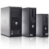
Your computer has a manual voltage-selection switch. NOTE: Your computer's power supply may or may not have a voltage selection switch. 5 Verify that most closely matches the AC power available in Japan is set correctly for the voltage that the voltage selection switch is 100 V. NOTICE: In Japan, ...the voltage selection switch must be set to the 115-V position even though the AC power available in your location. Computers with a voltage selection switch on the back of the computer, if your computer has a voltage selection switch...
Your computer has a manual voltage-selection switch. NOTE: Your computer's power supply may or may not have a voltage selection switch. 5 Verify that most closely matches the AC power available in Japan is set correctly for the voltage that the voltage selection switch is 100 V. NOTICE: In Japan, ...the voltage selection switch must be set to the 115-V position even though the AC power available in your location. Computers with a voltage selection switch on the back of the computer, if your computer has a voltage selection switch...
Quick Reference Guide
Page 40
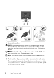
NOTICE: Be careful when opening the computer cover to ensure that you do not accidentally disconnect cables from the system board. 4 3 2 1 5 6 7 8 10 9 1 drive release latch 4 power supply 7 card slots (4) 10 front I/O panel 2 optical drive 5 chassis intrusion switch (optional) 8 heat sink assembly 3 floppy drive 6 system board 9 hard drive 40 Quick Reference Guide
NOTICE: Be careful when opening the computer cover to ensure that you do not accidentally disconnect cables from the system board. 4 3 2 1 5 6 7 8 10 9 1 drive release latch 4 power supply 7 card slots (4) 10 front I/O panel 2 optical drive 5 chassis intrusion switch (optional) 8 heat sink assembly 3 floppy drive 6 system board 9 hard drive 40 Quick Reference Guide

Quick Reference Guide
Page 44
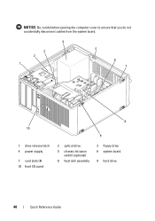
3 2 1 4 5 6 8 1 drive release latch 4 chassis intrusion switch (optional) 7 heat sink assembly 2 optical drive 5 system board 8 front I/O panel 7 3 power supply 6 card slots (3) 44 Quick Reference Guide
3 2 1 4 5 6 8 1 drive release latch 4 chassis intrusion switch (optional) 7 heat sink assembly 2 optical drive 5 system board 8 front I/O panel 7 3 power supply 6 card slots (3) 44 Quick Reference Guide
Quick Reference Guide
Page 48
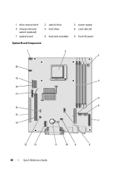
1 drive release latch 4 chassis intrusion switch (optional) 7 system board 2 optical drive 5 hard drive 8 heat sink assembly System Board Components 3 power supply 6 card slots (2) 9 front I/O panel 1 2 3 20 19 4 18 17 5 6 16 15 7 14 13 12 11 10 9 8 48 Quick Reference Guide
1 drive release latch 4 chassis intrusion switch (optional) 7 system board 2 optical drive 5 hard drive 8 heat sink assembly System Board Components 3 power supply 6 card slots (2) 9 front I/O panel 1 2 3 20 19 4 18 17 5 6 16 15 7 14 13 12 11 10 9 8 48 Quick Reference Guide
Quick Reference Guide
Page 55
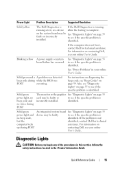
...power supply or system board failure has occurred. See "Power Problems" in the Product Information Guide. Also, see "Diagnostic Lights" on page 55 to see if the specific problem is identified. If the problem is not but the identified, contact Dell for technical assistance. Solid green power...your online User's Guide. If the computer does not boot, contact Dell for technical computer locks assistance. Power Light Problem Description Suggested Resolution Solid yellow The Dell Diagnostics is If the Dell Diagnostics is running, running a test, or a device allow the ...
...power supply or system board failure has occurred. See "Power Problems" in the Product Information Guide. Also, see "Diagnostic Lights" on page 55 to see if the specific problem is identified. If the problem is not but the identified, contact Dell for technical assistance. Solid green power...your online User's Guide. If the computer does not boot, contact Dell for technical computer locks assistance. Power Light Problem Description Suggested Resolution Solid yellow The Dell Diagnostics is If the Dell Diagnostics is running, running a test, or a device allow the ...

User's Guide
Page 4
Optical Drive 78 Processor 83 Removing the Processor 83 Installing the Processor 85 Power Supply 89 Replacing the Power Supply 89 DC Power Connectors 91 4 Desktop Computer 97 About Your Desktop Computer 97 Front View 97 Back View 98 Back-Panel Connectors 99 Inside Your Computer 101 System ... 125 PCI, PCI Express Cards, and PS/2 Serial Port Adapters 135 PCI Cards 135 PCI Express and DVI Cards 146 PS/2 Serial Port Adapters 163 Power Supply 169 Replacing the Power Supply 169 DC Power Connectors 171 Removing the Computer Cover 177 4 Contents
Optical Drive 78 Processor 83 Removing the Processor 83 Installing the Processor 85 Power Supply 89 Replacing the Power Supply 89 DC Power Connectors 91 4 Desktop Computer 97 About Your Desktop Computer 97 Front View 97 Back View 98 Back-Panel Connectors 99 Inside Your Computer 101 System ... 125 PCI, PCI Express Cards, and PS/2 Serial Port Adapters 135 PCI Cards 135 PCI Express and DVI Cards 146 PS/2 Serial Port Adapters 163 Power Supply 169 Replacing the Power Supply 169 DC Power Connectors 171 Removing the Computer Cover 177 4 Contents

User's Guide
Page 5
... 217 PCI, PCI Express Cards, and PS/2 Serial Port Adapters 223 PCI Cards 223 PCI Express and DVI Cards 227 PS/2 Serial Port Adapters 233 Power Supply 237 Replacing the Power Supply 237 DC Power Connectors 239 Processor 243 Removing the Processor 243 Installing the Processor 245 Contents 5
... 217 PCI, PCI Express Cards, and PS/2 Serial Port Adapters 223 PCI Cards 223 PCI Express and DVI Cards 227 PS/2 Serial Port Adapters 233 Power Supply 237 Replacing the Power Supply 237 DC Power Connectors 239 Processor 243 Removing the Processor 243 Installing the Processor 245 Contents 5

User's Guide
Page 27
3 2 1 4 5 1 optical drive 4 chassis intrusion switch (optional) 7 hard drive 2 floppy drive 5 system board 6 7 3 power supply 6 heat sink assembly Mini Tower Computer 27
3 2 1 4 5 1 optical drive 4 chassis intrusion switch (optional) 7 hard drive 2 floppy drive 5 system board 6 7 3 power supply 6 heat sink assembly Mini Tower Computer 27
User's Guide
Page 35
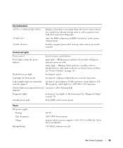
...light for a 1000-Mb (1-Gb) operation Activity light (on page 321). Standby power light AUX_PWR on the system board Power DC power supply: Wattage Heat dissipation Voltage Backup battery 305 W 1040.7 BTU/hr maximum manual selection power supplies-90 to 135 V at 50/60 Hz; 180 to run hard-drive and system... diagnostics starts the RAID setup menu if RAID is entered) Controls and Lights Power control front of chassis - Blinking green indicates sleep mode;...
...light for a 1000-Mb (1-Gb) operation Activity light (on page 321). Standby power light AUX_PWR on the system board Power DC power supply: Wattage Heat dissipation Voltage Backup battery 305 W 1040.7 BTU/hr maximum manual selection power supplies-90 to 135 V at 50/60 Hz; 180 to run hard-drive and system... diagnostics starts the RAID setup menu if RAID is entered) Controls and Lights Power control front of chassis - Blinking green indicates sleep mode;...
User's Guide
Page 89
... computer chassis. 1 Follow the procedures in the computer chassis as you remove them from being pinched or crimped. 3 Remove the four screws that attach the power supply to components inside your computer, discharge static electricity from your body before you replace them to prevent them from the system board and the drives...
... computer chassis. 1 Follow the procedures in the computer chassis as you remove them from being pinched or crimped. 3 Remove the four screws that attach the power supply to components inside your computer, discharge static electricity from your body before you replace them to prevent them from the system board and the drives...

User's Guide
Page 90
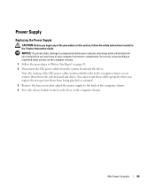
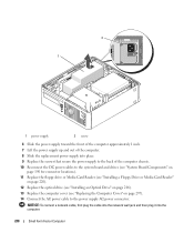
Mini Tower Computer 90 1 2 3 4 1 release button 4 AC power connector 2 power supply 3 screws (4) 5 Slide the power supply toward the front of the computer by approximately 1 inch. 6 Lift the power supply up and out of the computer. 7 Slide the replacement power supply into place. 8 Replace the screws that secure the power supply to the back of the computer chassis.
Mini Tower Computer 90 1 2 3 4 1 release button 4 AC power connector 2 power supply 3 screws (4) 5 Slide the power supply toward the front of the computer by approximately 1 inch. 6 Lift the power supply up and out of the computer. 7 Slide the replacement power supply into place. 8 Replace the screws that secure the power supply to the back of the computer chassis.
User's Guide
Page 101
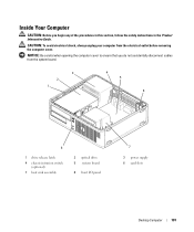
... shock, always unplug your computer from the system board. 3 2 1 4 5 6 8 1 drive release latch 4 chassis intrusion switch (optional) 7 heat sink assembly 2 optical drive 5 system board 8 front I/O panel 7 3 power supply 6 card slots Desktop Computer 101 NOTICE: Be careful when opening the computer cover to ensure that you begin any of the procedures in this section...
... shock, always unplug your computer from the system board. 3 2 1 4 5 6 8 1 drive release latch 4 chassis intrusion switch (optional) 7 heat sink assembly 2 optical drive 5 system board 8 front I/O panel 7 3 power supply 6 card slots Desktop Computer 101 NOTICE: Be careful when opening the computer cover to ensure that you begin any of the procedures in this section...
User's Guide
Page 109
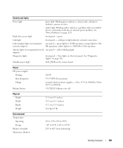
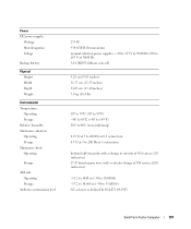
...panel - Blinking green indicates a sleep mode; Four lights on page 330. solid green indicates a power-on the system board Power DC power supply: Wattage Heat dissipation Voltage Backup battery 280 W 955.39 BTU/hr maximum manual selection power supplies - 90 to 135 V at 50/60 Hz; 180 to 265 V at 50/60 Hz 3-V...° to 95°F) -40° to 65°C (-40° to 149°F) 20% to 80% (noncondensing) Desktop Computer 109 Standby power light AUX_PWR on state. Controls and Lights Power light green light. Hard-drive access light front panel - green Link light front panel -
...panel - Blinking green indicates a sleep mode; Four lights on page 330. solid green indicates a power-on the system board Power DC power supply: Wattage Heat dissipation Voltage Backup battery 280 W 955.39 BTU/hr maximum manual selection power supplies - 90 to 135 V at 50/60 Hz; 180 to 265 V at 50/60 Hz 3-V...° to 95°F) -40° to 65°C (-40° to 149°F) 20% to 80% (noncondensing) Desktop Computer 109 Standby power light AUX_PWR on state. Controls and Lights Power light green light. Hard-drive access light front panel - green Link light front panel -

User's Guide
Page 169
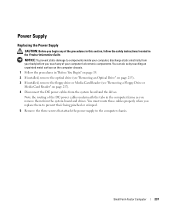
...remove them to prevent their being pinched or crimped. 3 Remove the two screws that attach the power supply to components inside your computer, discharge static electricity from the system board and the drives. Power Supply Replacing the Power Supply CAUTION: Before you touch any of the procedures in this section, follow the safety instructions located... carefully set it aside (see "Removing an Optical Drive" on page 115). 5 Press the release button located on page 19. 2 Disconnect the DC power cables from your body before you begin any of your computer's electronic components.
...remove them to prevent their being pinched or crimped. 3 Remove the two screws that attach the power supply to components inside your computer, discharge static electricity from the system board and the drives. Power Supply Replacing the Power Supply CAUTION: Before you touch any of the procedures in this section, follow the safety instructions located... carefully set it aside (see "Removing an Optical Drive" on page 115). 5 Press the release button located on page 19. 2 Disconnect the DC power cables from your body before you begin any of your computer's electronic components.
User's Guide
Page 170
... the front of the computer by approximately 1 inch. 7 Lift the power supply up and out of the computer. 8 Slide the replacement power supply into place. 9 Replace the screws that secure the power supply to the back of the computer chassis. 10 Reconnect the DC power cables (see "System Board Components" on page 102 for connector locations). 11...
... the front of the computer by approximately 1 inch. 7 Lift the power supply up and out of the computer. 8 Slide the replacement power supply into place. 9 Replace the screws that secure the power supply to the back of the computer chassis. 10 Reconnect the DC power cables (see "System Board Components" on page 102 for connector locations). 11...
User's Guide
Page 189
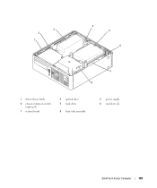
3 2 1 4 5 6 7 8 1 drive-release latch 4 chassis intrusion switch (optional) 7 system board 2 optical drive 5 hard drive 8 heat sink assembly 3 power supply 6 card slots (2) Small Form Factor Computer 189
3 2 1 4 5 6 7 8 1 drive-release latch 4 chassis intrusion switch (optional) 7 system board 2 optical drive 5 hard drive 8 heat sink assembly 3 power supply 6 card slots (2) Small Form Factor Computer 189
User's Guide
Page 197
... Storage Relative humidity Maximum vibration: Operating Storage Maximum shock: Operating Storage Altitude: Operating Storage Airborne contaminant level 275 W 938.85 BTU/hr maximum manual selection power supplies - 90 to 135 V at 50/60 Hz; 180 to 265 V at 50/60 Hz 3-V CR2032 lithium coin cell 9.26 cm (3.65 inches) 31.37 cm...
... Storage Relative humidity Maximum vibration: Operating Storage Maximum shock: Operating Storage Altitude: Operating Storage Airborne contaminant level 275 W 938.85 BTU/hr maximum manual selection power supplies - 90 to 135 V at 50/60 Hz; 180 to 265 V at 50/60 Hz 3-V CR2032 lithium coin cell 9.26 cm (3.65 inches) 31.37 cm...
User's Guide
Page 237
...in the computer frame as you remove them to prevent their being pinched or crimped. 5 Remove the three screws that attach the power supply to components inside your computer, discharge static electricity from your body before you touch any of your computer's electronic components. You ...them from the system board and the drives. NOTICE: To prevent static damage to the computer chassis. Small Form Factor Computer 237 Power Supply Replacing the Power Supply CAUTION: Before you begin any of the procedures in this section, follow the safety instructions located in "Before You Begin" on ...
...in the computer frame as you remove them to prevent their being pinched or crimped. 5 Remove the three screws that attach the power supply to components inside your computer, discharge static electricity from your body before you touch any of your computer's electronic components. You ...them from the system board and the drives. NOTICE: To prevent static damage to the computer chassis. Small Form Factor Computer 237 Power Supply Replacing the Power Supply CAUTION: Before you begin any of the procedures in this section, follow the safety instructions located in "Before You Begin" on ...
User's Guide
Page 238
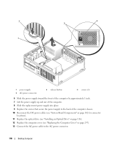
... plug it into place. 9 Replace the screws that secure the power supply to the back of the computer. 8 Slide the replacement power supply into the computer. 238 Small Form Factor Computer 2 1 1 power supply 2 screw 6 Slide the power supply toward the front of the computer approximately 1 inch. 7 Lift the power supply up and out of the computer chassis. 10 Reconnect the...
... plug it into place. 9 Replace the screws that secure the power supply to the back of the computer. 8 Slide the replacement power supply into the computer. 238 Small Form Factor Computer 2 1 1 power supply 2 screw 6 Slide the power supply toward the front of the computer approximately 1 inch. 7 Lift the power supply up and out of the computer chassis. 10 Reconnect the...

User's Guide
Page 249
.... Critical Fan Failure Cleared Advanced Features 249 ASF is designed to the administrator through system setup, Dell OpenManage™ IT Assistant, or Dell custom factory integration. 6 Advanced Features LegacySelect Technology Control LegacySelect technology control offers legacy-full, legacy-...available. Physical Security Violation/Chassis Intrusion - Cooling Device: Generic The fan speed (rpm) is too hot and the power supply has shut down. Control is provided to supersede previous operating-system-absent alerting technologies. CPU: Emergency Shutdown Event The...
.... Critical Fan Failure Cleared Advanced Features 249 ASF is designed to the administrator through system setup, Dell OpenManage™ IT Assistant, or Dell custom factory integration. 6 Advanced Features LegacySelect Technology Control LegacySelect technology control offers legacy-full, legacy-...available. Physical Security Violation/Chassis Intrusion - Cooling Device: Generic The fan speed (rpm) is too hot and the power supply has shut down. Control is provided to supersede previous operating-system-absent alerting technologies. CPU: Emergency Shutdown Event The...


