Quick Reference Guide
Page 55
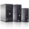
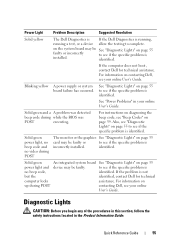
... 55 faulty or incorrectly to see if the specific problem is identified. Power Light Problem Description Suggested Resolution Solid yellow The Dell Diagnostics is If the Dell Diagnostics is running, running a test, or a device allow the testing to see if the specific problem is identified. See... be faulty. Solid green An integrated system board See "Diagnostic Lights" on up during POST contacting Dell, see if the specific problem is no video during while the BIOS was POST executing. Solid green power light, no beep code and no beep code, identified. Diagnostic...
... 55 faulty or incorrectly to see if the specific problem is identified. Power Light Problem Description Suggested Resolution Solid yellow The Dell Diagnostics is If the Dell Diagnostics is running, running a test, or a device allow the testing to see if the specific problem is identified. See... be faulty. Solid green An integrated system board See "Diagnostic Lights" on up during POST contacting Dell, see if the specific problem is no video during while the BIOS was POST executing. Solid green power light, no beep code and no beep code, identified. Diagnostic...
Quick Reference Guide
Page 56
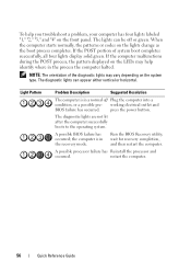
... the POST process, the pattern displayed on the LEDs may vary depending on the system type. working electrical outlet and BIOS failure has occurred. A possible BIOS failure has occurred; The diagnostic lights can be off Plug the computer into a condition, or a possible pre- The...lights are not lit after the computer successfully boots to the operating system. restart the computer. 56 Quick Reference Guide Run the BIOS Recovery utility, wait for recovery completion, and then restart the computer. Light Pattern Problem Description Suggested Resolution The computer is in ...
... the POST process, the pattern displayed on the LEDs may vary depending on the system type. working electrical outlet and BIOS failure has occurred. A possible BIOS failure has occurred; The diagnostic lights can be off Plug the computer into a condition, or a possible pre- The...lights are not lit after the computer successfully boots to the operating system. restart the computer. 56 Quick Reference Guide Run the BIOS Recovery utility, wait for recovery completion, and then restart the computer. Light Pattern Problem Description Suggested Resolution The computer is in ...

Quick Reference Guide
Page 60
...the option that best describes the problem and click Next to resolve the incompatibility. If your online User's Guide. Code Cause 2 short, 1 long BIOS checksum error 1 long, 2 short Memory test failure (bad memory during memory sizing) 1 long, 3 short, 2 short No memory 1 short key...Click Start and click Help and Support. 2 Type hardware troubleshooter in the search field and press to identify a more serious cause. 3 Contact Dell for technical assistance. Windows XP 1 Click Start→ Help and Support. 2 Type hardware troubleshooter in the search field and press to start...
...the option that best describes the problem and click Next to resolve the incompatibility. If your online User's Guide. Code Cause 2 short, 1 long BIOS checksum error 1 long, 2 short Memory test failure (bad memory during memory sizing) 1 long, 3 short, 2 short No memory 1 short key...Click Start and click Help and Support. 2 Type hardware troubleshooter in the search field and press to identify a more serious cause. 3 Contact Dell for technical assistance. Windows XP 1 Click Start→ Help and Support. 2 Type hardware troubleshooter in the search field and press to start...
User's Guide
Page 19
...have read the safety information in this document may require the following tools: • Small flat-blade screwdriver • Phillips screwdriver • Flash BIOS update program floppy disk, CD, USB key Turning Off Your Computer NOTICE: To avoid losing data, save and close any open files and exit ...any open programs before you turn them off now. Before You Begin 19 Recommended Tools The procedures in your Dell™ Product Information Guide. • A component can be done by performing the removal procedure in your computer and attached devices did not...
...have read the safety information in this document may require the following tools: • Small flat-blade screwdriver • Phillips screwdriver • Flash BIOS update program floppy disk, CD, USB key Turning Off Your Computer NOTICE: To avoid losing data, save and close any open files and exit ...any open programs before you turn them off now. Before You Begin 19 Recommended Tools The procedures in your Dell™ Product Information Guide. • A component can be done by performing the removal procedure in your computer and attached devices did not...
User's Guide
Page 31
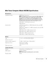
... Computer Information Chipset RAID support Data bus width nVidia GeForce 6150LE/Nforce 430 RAID 0 and RAID 1 NOTE: RAID support is therefore available only on the BIOS splash screen and the system setup program screens. Mini Tower Computer (Model #DCSM) Specifications .
... Computer Information Chipset RAID support Data bus width nVidia GeForce 6150LE/Nforce 430 RAID 0 and RAID 1 NOTE: RAID support is therefore available only on the BIOS splash screen and the system setup program screens. Mini Tower Computer (Model #DCSM) Specifications .
User's Guide
Page 32
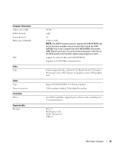
... 3.5-inch hard drives PCI 2.3 PCI Express 1.0A SATA 1.0A and 2.0 USB 2.0 Mini Tower Computer 32 Computer Information Address bus width DMA channels Interrupt levels BIOS chip (NVRAM) NIC Video Type Audio Type Stereo conversion Controllers Drives Expansion Bus Bus type 40 bits eight 24 8 Mb or 4 Mb NOTE: The AMD... Phenom processor requires the 8-Mb NVRAM chip and is therefore available only on the BIOS splash screen and the system setup program screens. If your computer has the 8-Mb NVRAM chip and the AMD Phenom processor, the word enhanced appears...
... 3.5-inch hard drives PCI 2.3 PCI Express 1.0A SATA 1.0A and 2.0 USB 2.0 Mini Tower Computer 32 Computer Information Address bus width DMA channels Interrupt levels BIOS chip (NVRAM) NIC Video Type Audio Type Stereo conversion Controllers Drives Expansion Bus Bus type 40 bits eight 24 8 Mb or 4 Mb NOTE: The AMD... Phenom processor requires the 8-Mb NVRAM chip and is therefore available only on the BIOS splash screen and the system setup program screens. If your computer has the 8-Mb NVRAM chip and the AMD Phenom processor, the word enhanced appears...

User's Guide
Page 105
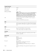
... Desktop Computer 105 If your computer has the 8-Mb NVRAM chip and the AMD Phenom processor, the word enhanced appears in the title on the BIOS splash screen and the system setup program screens. AMD Athlon™ 64 X2 Dual-Core processor AMD Athlon 64 AMD Phenom Quad-Core: 2-MB L2...
... Desktop Computer 105 If your computer has the 8-Mb NVRAM chip and the AMD Phenom processor, the word enhanced appears in the title on the BIOS splash screen and the system setup program screens. AMD Athlon™ 64 X2 Dual-Core processor AMD Athlon 64 AMD Phenom Quad-Core: 2-MB L2...
User's Guide
Page 106
... processor, the word enhanced appears in the title on models that include the 8-Mb NVRAM chip. Computer Information Address bus width DMA channels Interrupt levels BIOS chip (NVRAM) NIC Video Type Audio Type Stereo conversion Controllers Drives Expansion Bus Bus type Bus speed Cards 106 Desktop Computer 40 bits eight 24... 8 Mb or 4 Mb NOTE: The AMD Phenom processor requires the 8-Mb NVRAM chip and is therefore available only on the BIOS splash screen and the system setup program screens.
... processor, the word enhanced appears in the title on models that include the 8-Mb NVRAM chip. Computer Information Address bus width DMA channels Interrupt levels BIOS chip (NVRAM) NIC Video Type Audio Type Stereo conversion Controllers Drives Expansion Bus Bus type Bus speed Cards 106 Desktop Computer 40 bits eight 24... 8 Mb or 4 Mb NOTE: The AMD Phenom processor requires the 8-Mb NVRAM chip and is therefore available only on the BIOS splash screen and the system setup program screens.
User's Guide
Page 193
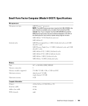
... bus width DMA channels AMD Phenom™ processors NOTE: The AMD Phenom processor requires the 8-Mb NVRAM chip and is therefore available only on the BIOS splash screen and the system setup program screens.
... bus width DMA channels AMD Phenom™ processors NOTE: The AMD Phenom processor requires the 8-Mb NVRAM chip and is therefore available only on the BIOS splash screen and the system setup program screens.
User's Guide
Page 194
... chip and the AMD Phenom processor, the word enhanced appears in the title on models that include the 8-Mb NVRAM chip. Computer Information Interrupt levels BIOS chip (NVRAM) NIC Video Type Audio Type Stereo conversion Controllers Drives Expansion Bus Bus type Bus speed Cards PCI connectors card size connector size 24... 8 Mb or 4 Mb NOTE: The AMD Phenom processor requires the 8-Mb NVRAM chip and is therefore available only on the BIOS splash screen and the system setup program screens.
... chip and the AMD Phenom processor, the word enhanced appears in the title on models that include the 8-Mb NVRAM chip. Computer Information Interrupt levels BIOS chip (NVRAM) NIC Video Type Audio Type Stereo conversion Controllers Drives Expansion Bus Bus type Bus speed Cards PCI connectors card size connector size 24... 8 Mb or 4 Mb NOTE: The AMD Phenom processor requires the 8-Mb NVRAM chip and is therefore available only on the BIOS splash screen and the system setup program screens.
User's Guide
Page 250
... out of your computer, such as updating its BIOS or shutting it is enabled, you must know the administrator password before you can reset the Chassis Intrusion setting. 250 Advanced Features Dell OpenManage Client Instrumentation Dell OpenManage Client Instrumentation is software that enables remote management...running. • Monitor the status of your computer. It supports instrumentation that conforms to do the following: • Access information about Dell's ASF implementation, see the ASF User's Guide and the ASF Administrator's Guide, which is based on DMI and CIM, is one...
... out of your computer, such as updating its BIOS or shutting it is enabled, you must know the administrator password before you can reset the Chassis Intrusion setting. 250 Advanced Features Dell OpenManage Client Instrumentation Dell OpenManage Client Instrumentation is software that enables remote management...running. • Monitor the status of your computer. It supports instrumentation that conforms to do the following: • Access information about Dell's ASF implementation, see the ASF User's Guide and the ASF Administrator's Guide, which is based on DMI and CIM, is one...
User's Guide
Page 258
...features that selection active. System System Info Processor Info Memory Info PCI Info Date/Time Boot Sequence HDD Boot Sequence Lists the computer name, BIOS Version, Service Tag, Express Service Code, (if applicable), and the Asset Tag. Lists the order that option and the option's current ...and Key Functions - In this list. This field contains information about that the BIOS will search the available hard drives in this field you can be modified. Scroll up and down -arrow keys. available settings. Options List...
...features that selection active. System System Info Processor Info Memory Info PCI Info Date/Time Boot Sequence HDD Boot Sequence Lists the computer name, BIOS Version, Service Tag, Express Service Code, (if applicable), and the Asset Tag. Lists the order that option and the option's current ...and Key Functions - In this list. This field contains information about that the BIOS will search the available hard drives in this field you can be modified. Scroll up and down -arrow keys. available settings. Options List...

User's Guide
Page 263
Event Log Allows you must be bootable. Off does not skip any steps during POST, the BIOS will display the error message and continue booting the system. On starts the system more quickly. On commands the right keypad keys to function as ...=Boot Menu). Boot Menu displays the Quickboot message only (F12=Boot Menu). When set to Report (enabled) and an error is detected during POST, the BIOS will display the error message and prompt you are booting to a USB device, connect the USB device to a USB connector (see "Front View" on page...
Event Log Allows you must be bootable. Off does not skip any steps during POST, the BIOS will display the error message and continue booting the system. On starts the system more quickly. On commands the right keypad keys to function as ...=Boot Menu). Boot Menu displays the Quickboot message only (F12=Boot Menu). When set to Report (enabled) and an error is detected during POST, the BIOS will display the error message and prompt you are booting to a USB device, connect the USB device to a USB connector (see "Front View" on page...

User's Guide
Page 264
.... Booting to a USB Device NOTE: To boot to a USB device, the device must be the 1st, 2nd, 3rd, or 4th Boot Device, (as applicable). The BIOS detects the device and adds the USB device option to the boot menu. 3 From the boot menu, select the number that your computer (see the...
.... Booting to a USB Device NOTE: To boot to a USB device, the device must be the 1st, 2nd, 3rd, or 4th Boot Device, (as applicable). The BIOS detects the device and adds the USB device option to the boot menu. 3 From the boot menu, select the number that your computer (see the...
User's Guide
Page 271
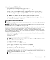
... Configuration" on page 273. Ideally, however, the drives should be used to wait until you see "System Setup Options" on how to enter the RAID BIOS. NOTE: If the operating system logo appears, continue to create a RAID configuration. then shut down -arrow keys to select a hard drive to include in the...
... Configuration" on page 273. Ideally, however, the drives should be used to wait until you see "System Setup Options" on how to enter the RAID BIOS. NOTE: If the operating system logo appears, continue to create a RAID configuration. then shut down -arrow keys to select a hard drive to include in the...
User's Guide
Page 272
... the array in the next step. 8 Press to clear all data on your hard drives (see "Converting From One RAID Configuration to exit the RAID BIOS. Creating a RAID Array NOTICE: The following procedure to migrate an existing RAID configuration (see "Setting Your Computer to keep before continuing. The Array Detail window...
... the array in the next step. 8 Press to clear all data on your hard drives (see "Converting From One RAID Configuration to exit the RAID BIOS. Creating a RAID Array NOTICE: The following procedure to migrate an existing RAID configuration (see "Setting Your Computer to keep before continuing. The Array Detail window...
User's Guide
Page 291
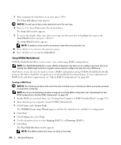
... 105 • "Small Form Factor Computer (Model # DCCY) Specifications" on page 193 NOTICE: Before you install new memory modules, download the most recent BIOS for your computer from Dell is covered under your computer, see the "Memory" section of matched memory modules installed in connectors DIMM1 and DIMM2 or • A memory module.... NOTE: Always install DDR2 memory modules in the upper-right corner of the module to boot or otherwise impact performance. NOTE: Memory purchased from the Dell Support website at support...
... 105 • "Small Form Factor Computer (Model # DCCY) Specifications" on page 193 NOTICE: Before you install new memory modules, download the most recent BIOS for your computer from Dell is covered under your computer, see the "Memory" section of matched memory modules installed in connectors DIMM1 and DIMM2 or • A memory module.... NOTE: Always install DDR2 memory modules in the upper-right corner of the module to boot or otherwise impact performance. NOTE: Memory purchased from the Dell Support website at support...
User's Guide
Page 293
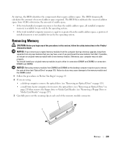
...should install your original memory modules in pairs either in the Product Information Guide. Removing Memory CAUTION: Before you purchased the new modules from Dell. NOTICE: Removing memory modules from 4 GB to determine the amount of usable space. • If the total installed computer memory is less... Reader. (see "Optical Drive" on page 217). 3 Carefully press out the securing clip at each end of reserved address space required. The BIOS dynamically calculates the amount of the memory module connector. 2 1 Memory 293 At start properly. If possible, do so may cause damage to or...
...should install your original memory modules in pairs either in the Product Information Guide. Removing Memory CAUTION: Before you purchased the new modules from Dell. NOTICE: Removing memory modules from 4 GB to determine the amount of usable space. • If the total installed computer memory is less... Reader. (see "Optical Drive" on page 217). 3 Carefully press out the securing clip at each end of reserved address space required. The BIOS dynamically calculates the amount of the memory module connector. 2 1 Memory 293 At start properly. If possible, do so may cause damage to or...
User's Guide
Page 318
... Problems NO DRIVE LETTER IS ASSIGNED - There is a FlexBay disable option in the BIOS setup. When Microsoft Windows XP detects the media card reader, the device is enabled in the BIOS setup that is installed. If the next logical drive after all tests run successfully, the... in the media card reader is related to the media card reader. NOTE: Each slot in the system. CAUTION: Before you are prompted to see "Dell Diagnostics" on page 351 as the next logical drive after the physical drives is not running, check to insert media. R U N TH E D E L L D I A G N O S T I C...
... Problems NO DRIVE LETTER IS ASSIGNED - There is a FlexBay disable option in the BIOS setup. When Microsoft Windows XP detects the media card reader, the device is enabled in the BIOS setup that is installed. If the next logical drive after all tests run successfully, the... in the media card reader is related to the media card reader. NOTE: Each slot in the system. CAUTION: Before you are prompted to see "Dell Diagnostics" on page 351 as the next logical drive after the physical drives is not running, check to insert media. R U N TH E D E L L D I A G N O S T I C...

User's Guide
Page 330
... where in the process the computer halted. If the computer malfunctions during POST A problem was detected while the BIOS was executing. A possible BIOS failure has occurred; Reinstall the processor and restart the computer. 330 Troubleshooting Tools and Utilities Also, check the ..."4" on the system type. A possible processor failure has occurred. the Run the BIOS Recovery utility, wait for computer is identified (see if the specific problem is not identified, contact Dell for instructions on the lights change as the boot process completes. Power Light Problem ...
... where in the process the computer halted. If the computer malfunctions during POST A problem was detected while the BIOS was executing. A possible BIOS failure has occurred; Reinstall the processor and restart the computer. 330 Troubleshooting Tools and Utilities Also, check the ..."4" on the system type. A possible processor failure has occurred. the Run the BIOS Recovery utility, wait for computer is identified (see if the specific problem is not identified, contact Dell for instructions on the lights change as the boot process completes. Power Light Problem ...


