User Manual
Page 1
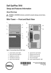
... Mini-Tower 1. microphone connector 5. power button, power light 2. Mini-Tower - power supply diagnostic light Regulatory Model: D05D, D09M, D03S, D01U Regulatory Type: D05D002, D09M003, D03S002, D01U003 2011 - 12 optical drive (optional) 6. USB 2.0 connectors (2) 8. Front and Back View Figure 1. optical-drive eject button 7. USB 3.0 connectors (2) 9. headphone connector 4. optical-drive bay (optional) 3. Dell OptiPlex 7010 Setup and Features Information...
... Mini-Tower 1. microphone connector 5. power button, power light 2. Mini-Tower - power supply diagnostic light Regulatory Model: D05D, D09M, D03S, D01U Regulatory Type: D05D002, D09M003, D03S002, D01U003 2011 - 12 optical drive (optional) 6. USB 2.0 connectors (2) 8. Front and Back View Figure 1. optical-drive eject button 7. USB 3.0 connectors (2) 9. headphone connector 4. optical-drive bay (optional) 3. Dell OptiPlex 7010 Setup and Features Information...
User Manual
Page 2
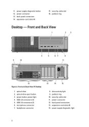
... 7. security-cable slot 11. security-cable slot 16. drive activity light 9. padlock ring 10. expansion-card slots (4) 14. headphone connector 8. power button, power light 4. power connector 12. power supply diagnostic button 12. USB 3.0 connectors (2) 6. power supply diagnostic light 2 11. back panel connectors 14. expansion-card slots (4) 15. padlock ring Desktop - Front and Back View Of Desktop 1. optical...
... 7. security-cable slot 11. security-cable slot 16. drive activity light 9. padlock ring 10. expansion-card slots (4) 14. headphone connector 8. power button, power light 4. power connector 12. power supply diagnostic button 12. USB 3.0 connectors (2) 6. power supply diagnostic light 2 11. back panel connectors 14. expansion-card slots (4) 15. padlock ring Desktop - Front and Back View Of Desktop 1. optical...
User Manual
Page 3
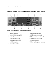
15. USB 2.0 connectors (2) 6. line-out connector 8. DisplayPort connectors (2) 11. USB 3.0 connectors (2) 12. network connector 4. USB 2.0 connectors (2) 10. mouse connector 2. network activity light 5. line-in/microphone connector 3 network link integrity light 3. keyboard connector 9. Back Panel View of Mini-Tower And Desktop 1. serial connector 7. VGA connector 13. Back Panel View Figure 3. power supply diagnostic button Mini-Tower and Desktop -
15. USB 2.0 connectors (2) 6. line-out connector 8. DisplayPort connectors (2) 11. USB 3.0 connectors (2) 12. network connector 4. USB 2.0 connectors (2) 10. mouse connector 2. network activity light 5. line-in/microphone connector 3 network link integrity light 3. keyboard connector 9. Back Panel View of Mini-Tower And Desktop 1. serial connector 7. VGA connector 13. Back Panel View Figure 3. power supply diagnostic button Mini-Tower and Desktop -

User Manual
Page 4
Small Form Factor - Front and Back View Of Small Form Factor 1. power button, power light 4. microphone connector 7. expansion-card slots (2) 4 power supply diagnostic light 14. Front and Back View Figure 4. padlock ring 10. back panel connectors 15. optical drive 2. drive activity light 9. USB 3.0 connectors (2) 6. headphone connector 8. security-cable slot 11. optical-drive eject button 3. power connector 12. power supply diagnostic button 13. USB 2.0 connectors (2) 5.
Small Form Factor - Front and Back View Of Small Form Factor 1. power button, power light 4. microphone connector 7. expansion-card slots (2) 4 power supply diagnostic light 14. Front and Back View Figure 4. padlock ring 10. back panel connectors 15. optical drive 2. drive activity light 9. USB 3.0 connectors (2) 6. headphone connector 8. security-cable slot 11. optical-drive eject button 3. power connector 12. power supply diagnostic button 13. USB 2.0 connectors (2) 5.

User Manual
Page 9
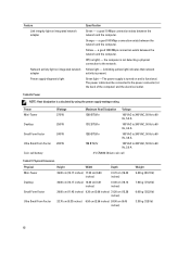
Power Voltage Coin-cell battery Wattage Maximum heat dissipation Mini-Tower 275 W 938.30 BTU/hr Desktop Small Form Factor 100 ...A / 2,90 A Finding More Information and Resources See the safety and regulatory documents that shipped with your computer and the regulatory compliance website at www.dell.com/regulatory_compliance for more information on: 9 Physical Height Width Depth Weight (minimum) Mini-Tower 360 mm (14.17 inches) 175 mm (6.89 inches) ...818.89 BTU/hr Ultra Small Form Factor 200 W 682.40 BTU/hr NOTE: Heat dissipation is calculated by using the power supply wattage rating.
Power Voltage Coin-cell battery Wattage Maximum heat dissipation Mini-Tower 275 W 938.30 BTU/hr Desktop Small Form Factor 100 ...A / 2,90 A Finding More Information and Resources See the safety and regulatory documents that shipped with your computer and the regulatory compliance website at www.dell.com/regulatory_compliance for more information on: 9 Physical Height Width Depth Weight (minimum) Mini-Tower 360 mm (14.17 inches) 175 mm (6.89 inches) ...818.89 BTU/hr Ultra Small Form Factor 200 W 682.40 BTU/hr NOTE: Heat dissipation is calculated by using the power supply wattage rating.
Owner's Manual (Desktop)
Page 3
... Hard Drive...15 Removing The Optical Drive...15 Installing The Optical Drive...17 Removing The Speaker...17 Installing The Speaker...18 Removing The Power Supply Unit...18 Installing The Power Supply Unit...22 Removing The Heat Sink...23 Installing The Heat Sink...24 Removing The Processor...24 Installing The Processor...25 Removing The System...
... Hard Drive...15 Removing The Optical Drive...15 Installing The Optical Drive...17 Removing The Speaker...17 Installing The Speaker...18 Removing The Power Supply Unit...18 Installing The Power Supply Unit...22 Removing The Heat Sink...23 Installing The Heat Sink...24 Removing The Processor...24 Installing The Processor...25 Removing The System...

Owner's Manual (Desktop)
Page 18
Press down the speaker-securing tab and slide the speaker upwards to remove it . 2. Removing The Power Supply Unit 1. Press the speaker-securing tab and slide the speaker downward to the system board. 4. Installing The Speaker 1. Connect the speaker cable to secure it . Follow the procedures in After Working Inside Your Computer. Install the cover. 5. Remove the a) cover b) hard drive c) optical drive 18 4. Thread the speaker cable into the chassis clip. 3. Follow the procedures in Before Working Inside Your Computer. 2.
Press down the speaker-securing tab and slide the speaker upwards to remove it . 2. Removing The Power Supply Unit 1. Press the speaker-securing tab and slide the speaker downward to the system board. 4. Installing The Speaker 1. Connect the speaker cable to secure it . Follow the procedures in After Working Inside Your Computer. Install the cover. 5. Remove the a) cover b) hard drive c) optical drive 18 4. Thread the speaker cable into the chassis clip. 3. Follow the procedures in Before Working Inside Your Computer. 2.

Owner's Manual (Desktop)
Page 21
Unthread the power supply cables from the chassis clip. 8. Remove the screws that secure the power supply unit to the back of the computer. 21 7. Push in on the blue release tab beside the power supply, and slide the power supply towards the front of the computer. 9.
Unthread the power supply cables from the chassis clip. 8. Remove the screws that secure the power supply unit to the back of the computer. 21 7. Push in on the blue release tab beside the power supply, and slide the power supply towards the front of the computer. 9.

Owner's Manual (Desktop)
Page 22
Install the hard drive. 8. Connect the 4-pin power cable to the system board. 6. Install the cover. 9. Tighten the screws securing the power supply to secure it. 2. Place the power supply in After Working Inside Your Computer. 22 Connect the 24-pin power cable to the system board. 5. 10. Thread the power supply cables into the chassis clips. 4. Install the optical drive. 7. Lift the power supply out of the computer. 3. Installing The Power Supply Unit 1. Follow the procedures in the chassis and slide towards the back of the system to the back of the computer.
Install the hard drive. 8. Connect the 4-pin power cable to the system board. 6. Install the cover. 9. Tighten the screws securing the power supply to secure it. 2. Place the power supply in After Working Inside Your Computer. 22 Connect the 24-pin power cable to the system board. 5. 10. Thread the power supply cables into the chassis clips. 4. Install the optical drive. 7. Lift the power supply out of the computer. 3. Installing The Power Supply Unit 1. Follow the procedures in the chassis and slide towards the back of the system to the back of the computer.
Owner's Manual (Desktop)
Page 45
...default. This option is disabled by default. NOTE: When enabled, the fan runs at full speed. Allows the system to AC power supply. This option is connected to be enabled in operating system environment. • Block Sleep (S3 state) - Specifies whether keyboard.... Virtualization Support Option Virtualization VT for direct I /O Description This option specifies whether a Virtual Machine Monitor (VMM) can be powered on screen displays a message, that displays the keystroke sequence required to wake the computer from utilizing the additional hardware capabilities provided ...
...default. This option is disabled by default. NOTE: When enabled, the fan runs at full speed. Allows the system to AC power supply. This option is connected to be enabled in operating system environment. • Block Sleep (S3 state) - Specifies whether keyboard.... Virtualization Support Option Virtualization VT for direct I /O Description This option specifies whether a Virtual Machine Monitor (VMM) can be powered on screen displays a message, that displays the keystroke sequence required to wake the computer from utilizing the additional hardware capabilities provided ...

Owner's Manual (Desktop)
Page 53
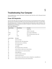
Table 13. The repeated pattern has a long pause inserted in sleep state blinking off power supply unit (PSU) failure steady off PSU is working but failed to 7. 5 Troubleshooting Your Computer You can troubleshoot your computer... For example 2,3 = 2 amber blinks, short pause, 3 amber blinks followed by a short pause then x number of the chassis also functions as a bicolored diagnostic LED. Power LED Diagnostics The power button LED located on Amber LED State 2,1 2,2 2,3 2, 4 2,5 2,6 2,7 3,1 3,2 3,3 3,4 3,5 3,6 Description system board failure system board, PSU or PSU cabling ...
Table 13. The repeated pattern has a long pause inserted in sleep state blinking off power supply unit (PSU) failure steady off PSU is working but failed to 7. 5 Troubleshooting Your Computer You can troubleshoot your computer... For example 2,3 = 2 amber blinks, short pause, 3 amber blinks followed by a short pause then x number of the chassis also functions as a bicolored diagnostic LED. Power LED Diagnostics The power button LED located on Amber LED State 2,1 2,2 2,3 2, 4 2,5 2,6 2,7 3,1 3,2 3,3 3,4 3,5 3,6 Description system board failure system board, PSU or PSU cabling ...
Owner's Manual (Desktop)
Page 62
...computer) and the electrical outlet. Off (no light) - Table 26. Orange - the computer is calculated by using the power supply wattage rating. The power cable must be connected to 60 Hz, 2.9 A 3 V CR2032 lithium coin cell Table 27. Physical Dimension Physical Height Width...) 3.30 kg (7.28 lb) 62 Yellow - Green light - Power NOTE: Heat dissipation is not detecting a physical connection to the network. Yellow light - The power supply is turned on integrated network adapter Power supply diagnostic light Specification Green - Feature Link integrity light on integrated network ...
...computer) and the electrical outlet. Off (no light) - Table 26. Orange - the computer is calculated by using the power supply wattage rating. The power cable must be connected to 60 Hz, 2.9 A 3 V CR2032 lithium coin cell Table 27. Physical Dimension Physical Height Width...) 3.30 kg (7.28 lb) 62 Yellow - Green light - Power NOTE: Heat dissipation is not detecting a physical connection to the network. Yellow light - The power supply is turned on integrated network adapter Power supply diagnostic light Specification Green - Feature Link integrity light on integrated network ...

Owner's Manual (Mini-Tower)
Page 3
... the Hard Drive...15 Removing the Optical Drive...15 Installing the Optical Drive...17 Removing the Speaker...17 Installing the Speaker...18 Removing the Power Supply...18 Installing the Power Supply...21 Removing the Heat Sink...21 Installing the Heat Sink...22 Removing the Processor...23 Installing the Processor...23 Removing the System Fan...
... the Hard Drive...15 Removing the Optical Drive...15 Installing the Optical Drive...17 Removing the Speaker...17 Installing the Speaker...18 Removing the Power Supply...18 Installing the Power Supply...21 Removing the Heat Sink...21 Installing the Heat Sink...22 Removing the Processor...23 Installing the Processor...23 Removing the System Fan...

Owner's Manual (Mini-Tower)
Page 18
Release and disconnect the power cable from the optical drive(s). 18 Slide the speaker downwards into the chassis clip and connect the speaker cable to the system board. 3. Installing the Speaker 1. Install the cover. 4. Remove the cover. 3. 4. Thread the speaker cable into its slot to remove. Removing the Power Supply 1. Follow the procedures in After Working Inside Your Computer. Press down the speaker-securing tab and slide the speaker upwards to secure it. 2. Follow the procedures in Before Working Inside Your Computer. 2.
Release and disconnect the power cable from the optical drive(s). 18 Slide the speaker downwards into the chassis clip and connect the speaker cable to the system board. 3. Installing the Speaker 1. Install the cover. 4. Remove the cover. 3. 4. Thread the speaker cable into its slot to remove. Removing the Power Supply 1. Follow the procedures in After Working Inside Your Computer. Press down the speaker-securing tab and slide the speaker upwards to secure it. 2. Follow the procedures in Before Working Inside Your Computer. 2.

Owner's Manual (Mini-Tower)
Page 19
Disconnect the 24-pin cable from the clip. Disconnect the power cable from the hard drive(s) and release it from the system board. 5. Remove the screws that secure the power supply to the back of the computer. 19 Disconnect the 4-pin power cable from the system board. 6. 4.
Disconnect the 24-pin cable from the clip. Disconnect the power cable from the hard drive(s) and release it from the system board. 5. Remove the screws that secure the power supply to the back of the computer. 19 Disconnect the 4-pin power cable from the system board. 6. 4.

Owner's Manual (Mini-Tower)
Page 20
7. Push in on the blue release tab beside the power supply, and slide the power supply towards the front of the computer. 20 Lift the power supply out of the computer. 8.
7. Push in on the blue release tab beside the power supply, and slide the power supply towards the front of the computer. 20 Lift the power supply out of the computer. 8.

Owner's Manual (Mini-Tower)
Page 21
...Power Supply 1. Place the power supply in the chassis and slide towards the back of the computer. 3. Install the cover. 8. Follow the procedures in Before Working Inside Your Computer. 2. Connect the power cables to the system board. 4. Connect the 4-pin power cable to the hard drive(s) and optical drive(s). 7. Connect the 24-pin power.... Remove the cover. 3. Thread the power cables into the chassis clips. 6. Press the plastic clip to the system board. 5. Use a Phillips screwdriver to tighten the screws securing the power supply to the back of the system to secure...
...Power Supply 1. Place the power supply in the chassis and slide towards the back of the computer. 3. Install the cover. 8. Follow the procedures in Before Working Inside Your Computer. 2. Connect the power cables to the system board. 4. Connect the 4-pin power cable to the hard drive(s) and optical drive(s). 7. Connect the 24-pin power.... Remove the cover. 3. Thread the power cables into the chassis clips. 6. Press the plastic clip to the system board. 5. Use a Phillips screwdriver to tighten the screws securing the power supply to the back of the system to secure...

Owner's Manual (Mini-Tower)
Page 41
This option allows you block entering to AC power supply. The options differ based on by default. Allows the system to power on by special LAN signals when it boots. Table 7. Table 8. Controls the speed of the system fan. This feature only works when ... technology. • Enable Intel Virtualization Technology - Specifies whether the sign-on screen displays a message, that displays the keystroke sequence required to be powered on by special LAN or WLAN signals. (For Ultra Small Form Factor only) This option is enabled by default. This option is connected to ...
This option allows you block entering to AC power supply. The options differ based on by default. Allows the system to power on by special LAN signals when it boots. Table 7. Table 8. Controls the speed of the system fan. This feature only works when ... technology. • Enable Intel Virtualization Technology - Specifies whether the sign-on screen displays a message, that displays the keystroke sequence required to be powered on by special LAN or WLAN signals. (For Ultra Small Form Factor only) This option is enabled by default. This option is connected to ...
Owner's Manual (Mini-Tower)
Page 49
... computer. Amber LED blinking scheme - The repeated pattern has a long pause inserted in sleep state blinking off power supply unit (PSU) failure steady off steady system is only active and visible during the operation of the chassis also functions... 13. 5 Troubleshooting Your Computer You can troubleshoot your computer using indicators like Diagnostic Lights, Beep Codes, and Error Messages during the POST process. Power LED Diagnostics The power button LED located on Amber LED State 2,1 2,2 2,3 2, 4 2,5 2,6 2,7 3,1 3,2 3,3 3,4 3,5 3,6 Description system board failure system ...
... computer. Amber LED blinking scheme - The repeated pattern has a long pause inserted in sleep state blinking off power supply unit (PSU) failure steady off steady system is only active and visible during the operation of the chassis also functions... 13. 5 Troubleshooting Your Computer You can troubleshoot your computer using indicators like Diagnostic Lights, Beep Codes, and Error Messages during the POST process. Power LED Diagnostics The power button LED located on Amber LED State 2,1 2,2 2,3 2, 4 2,5 2,6 2,7 3,1 3,2 3,3 3,4 3,5 3,6 Description system board failure system ...

Owner's Manual (Mini-Tower)
Page 58
Yellow light - A blinking yellow light indicates that network activity is functional. The power supply is turned on integrated network adapter Power supply diagnostic light Specification Green - Power Mini-Tower Wattage 275 W Desktop 250 W Small Form Factor 240 W Ultra Small Form Factor 200 W Coin-... the network. a good 10 Mbps connection exists between the network and the computer. Yellow - the computer is calculated by using the power supply wattage rating. Green light - Table 26. Physical Dimension Physical Height Width Depth Mini-Tower 36.00 cm (14.17 inches) 17.50...
Yellow light - A blinking yellow light indicates that network activity is functional. The power supply is turned on integrated network adapter Power supply diagnostic light Specification Green - Power Mini-Tower Wattage 275 W Desktop 250 W Small Form Factor 240 W Ultra Small Form Factor 200 W Coin-... the network. a good 10 Mbps connection exists between the network and the computer. Yellow - the computer is calculated by using the power supply wattage rating. Green light - Table 26. Physical Dimension Physical Height Width Depth Mini-Tower 36.00 cm (14.17 inches) 17.50...


