Small Form Factor Service Manual
Page 4
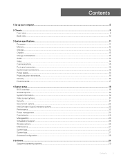
... Removing processor...52 Installing the processor...53 M.2 PCIe SSD ...54 Removing the M.2 PCIe SSD ...54 Installing the M.2 PCIe SSD...55 Power supply unit...56 Removing power supply unit or PSU...56 Installing the power supply unit or PSU...58 Speaker...60 Removing speaker...60 Installing the speaker...61 System board...62 Removing system board...62 Installing...
... Removing processor...52 Installing the processor...53 M.2 PCIe SSD ...54 Removing the M.2 PCIe SSD ...54 Installing the M.2 PCIe SSD...55 Power supply unit...56 Removing power supply unit or PSU...56 Installing the power supply unit or PSU...58 Speaker...60 Removing speaker...60 Installing the speaker...61 System board...62 Removing system board...62 Installing...
Small Form Factor Service Manual
Page 15
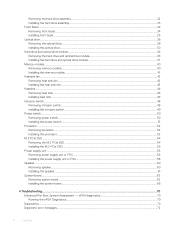
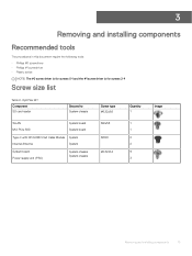
Screw size list Component WLAN SSD card Power supply unit (PSU) IO module Internal antenna Card reader HDD Caddy Stand-Off System board Front IO bracket M2x3.5 1 1 M3X3 2 2 M3X5 2 1 M3X6 1 6-32X1/4" 3 5 1 Removing and installing components 15 3 Removing and installing components Recommended tools The procedures in this document require the following tools: • Phillips #0 screwdriver • Phillips #1 screwdriver • Plastic scribe NOTE: The #0 screw driver is for screws 0-1 and the #1 screw driver is for screws 2-4 Screw size list Table 2.
Screw size list Component WLAN SSD card Power supply unit (PSU) IO module Internal antenna Card reader HDD Caddy Stand-Off System board Front IO bracket M2x3.5 1 1 M3X3 2 2 M3X5 2 1 M3X6 1 6-32X1/4" 3 5 1 Removing and installing components 15 3 Removing and installing components Recommended tools The procedures in this document require the following tools: • Phillips #0 screwdriver • Phillips #1 screwdriver • Plastic scribe NOTE: The #0 screw driver is for screws 0-1 and the #1 screw driver is for screws 2-4 Screw size list Table 2.
Small Form Factor Service Manual
Page 56
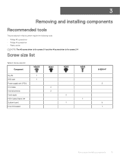
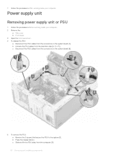
Power supply unit Removing power supply unit or PSU 1 Follow the procedure in After working inside your computer. 2 Remove the: a Side cover b Front bezel c HDD assembly d Hard drive and optical drive module e Heat sink fan 56 Removing and installing components 4 Install the: a Hard drive and optical drive module b HDD assembly c Front bezel d Side cover 5 Follow the procedure in Before working inside your computer.
Power supply unit Removing power supply unit or PSU 1 Follow the procedure in After working inside your computer. 2 Remove the: a Side cover b Front bezel c HDD assembly d Hard drive and optical drive module e Heat sink fan 56 Removing and installing components 4 Install the: a Hard drive and optical drive module b HDD assembly c Front bezel d Side cover 5 Follow the procedure in Before working inside your computer.
Small Form Factor Service Manual
Page 58
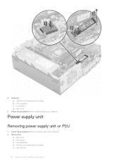
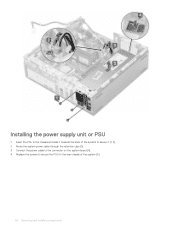
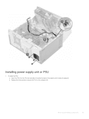
Installing the power supply unit or PSU 1 Insert the PSU in the chassis and slide it towards the back of the system to secure it [1, 2]. 2 Route the system power cable through the retention clips [3]. 3 Connect the power cable to the connector on the system board [4]. 4 Replace the screws to secure the PSU to the rear chassis of the system [5]. 58 Removing and installing components
Installing the power supply unit or PSU 1 Insert the PSU in the chassis and slide it towards the back of the system to secure it [1, 2]. 2 Route the system power cable through the retention clips [3]. 3 Connect the power cable to the connector on the system board [4]. 4 Replace the screws to secure the PSU to the rear chassis of the system [5]. 58 Removing and installing components
Tower Service Manual
Page 4
......41 Removing optional VGA module...41 Installing optional VGA module...42 Power supply unit...44 Removing power supply unit or PSU...44 Installing power supply unit or PSU...45 Intrusion switch...47 Removing intrusion switch...47 Installing intrusion switch...48 Power button...49 Removing power button...49 Installing power button...51 Speaker...53 Removing speaker...53 Installing speaker...54...
......41 Removing optional VGA module...41 Installing optional VGA module...42 Power supply unit...44 Removing power supply unit or PSU...44 Installing power supply unit or PSU...45 Intrusion switch...47 Removing intrusion switch...47 Installing intrusion switch...48 Power button...49 Removing power button...49 Installing power button...51 Speaker...53 Removing speaker...53 Installing speaker...54...
Tower Service Manual
Page 15
OptiPlex MT Component SD card reader Secured to System chassis Screw type #6.32x3.6 Quantity 1 Image WLAN M.2 PCIe SSD System board M2x3.5 1 System board 1 Type-C with DP/HDMI/VGA Cable Module System Internal Antenna System M3X3 2 2 System board Power supply unit (PSU) System chassis #6.32X1.4 9 System chassis 3 Removing and installing components 15 3 Removing and installing...
OptiPlex MT Component SD card reader Secured to System chassis Screw type #6.32x3.6 Quantity 1 Image WLAN M.2 PCIe SSD System board M2x3.5 1 System board 1 Type-C with DP/HDMI/VGA Cable Module System Internal Antenna System M3X3 2 2 System board Power supply unit (PSU) System chassis #6.32X1.4 9 System chassis 3 Removing and installing components 15 3 Removing and installing...
Tower Service Manual
Page 44
Power supply unit Removing power supply unit or PSU 1 Follow the procedure in After working inside your computer. 2 Remove the: a Side cover b Front bezel 3 Open the front panel door. 4 To release ...
Power supply unit Removing power supply unit or PSU 1 Follow the procedure in After working inside your computer. 2 Remove the: a Side cover b Front bezel 3 Open the front panel door. 4 To release ...
Tower Service Manual
Page 45
b Replace the three screws to secure the PSU to the computer [2] . Installing power supply unit or PSU 1 To install the PSU: a Insert the PSU into the PSU slot and slide it towards the back of the system until it clicks into place [1]. Removing and installing components 45
b Replace the three screws to secure the PSU to the computer [2] . Installing power supply unit or PSU 1 To install the PSU: a Insert the PSU into the PSU slot and slide it towards the back of the system until it clicks into place [1]. Removing and installing components 45
Tower Setup and specifications guide
Page 3
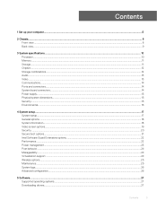
......12 Chipset...13 Storage combinations...13 Audio...14 Video...14 Communications...15 Ports and connectors...15 System board connectors...15 Power supply...16 Physical system dimensions...16 Security...16 Environmental...17 4 System setup...18 BIOS overview...18 General options...19 System ...information...19 Video screen options...21 Security...21 Secure boot options...22 Intel Software Guard Extensions options...23 Performance...23 Power management...24 Post behavior...25 Manageability...26 Virtualization support...26 Wireless options...26 Maintenance...27 System logs...27 System logs......
......12 Chipset...13 Storage combinations...13 Audio...14 Video...14 Communications...15 Ports and connectors...15 System board connectors...15 Power supply...16 Physical system dimensions...16 Security...16 Environmental...17 4 System setup...18 BIOS overview...18 General options...19 System ...information...19 Video screen options...21 Security...21 Secure boot options...22 Intel Software Guard Extensions options...23 Performance...23 Power management...24 Post behavior...25 Manageability...26 Virtualization support...26 Wireless options...26 Maintenance...27 System logs...27 System logs......
Tower Setup and specifications guide
Page 10
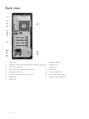
Back view 1 Line-out port 2 Serial Port (optional) 3 DisplayPort/HDMI 2.0b/VGA/USB Type-C Alt-Mode (optional) 4 DisplayPorts (2) 5 USB 3.1 Gen 1 ports (4) 6 Service tag 7 USB 2.0 ports (2) (supports SmartPower On) 8 Network port 9 Expansion card slots (4) 10 Power connector port 11 External antenna connectors (2) (optional) 12 Power supply diagnostic light 13 Release latch 14 Kensington security cable slot 15 Padlock ring 10 Chassis
Back view 1 Line-out port 2 Serial Port (optional) 3 DisplayPort/HDMI 2.0b/VGA/USB Type-C Alt-Mode (optional) 4 DisplayPorts (2) 5 USB 3.1 Gen 1 ports (4) 6 Service tag 7 USB 2.0 ports (2) (supports SmartPower On) 8 Network port 9 Expansion card slots (4) 10 Power connector port 11 External antenna connectors (2) (optional) 12 Power supply diagnostic light 13 Release latch 14 Kensington security cable slot 15 Padlock ring 10 Chassis
Tower Setup and specifications guide
Page 11
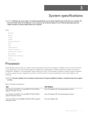
...8226; Video • Communications • Ports and connectors • System board connectors • Power supply • Physical system dimensions • Security • Environmental Processor Global Standard Products (GSP) are a subset of Dell's relationship products that are not a measure of performance. The following specifications are only those required ... below will be made available to implement global IT standards by region. They also enable companies to Dell customers. Table 2. Processor specifications Type Intel Pentium Gold G5400 (2 Cores/4MB/4T/3.7GHz/65W);
...8226; Video • Communications • Ports and connectors • System board connectors • Power supply • Physical system dimensions • Security • Environmental Processor Global Standard Products (GSP) are a subset of Dell's relationship products that are not a measure of performance. The following specifications are only those required ... below will be made available to implement global IT standards by region. They also enable companies to Dell customers. Table 2. Processor specifications Type Intel Pentium Gold G5400 (2 Cores/4MB/4T/3.7GHz/65W);
Tower Setup and specifications guide
Page 16
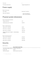
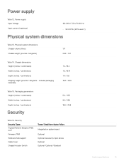
Power supply Input Voltage Input current (maximum) 90-264 VAC, 47 Hz/63 Hz • 260 W PSU (EPA Bronze) • 260 W PSU (EPA Platinum) Physical system dimensions ... system dimensions Chassis volume (liters) Chassis weight (pounds / kilograms) 14.77 17.49/7.93 Table 14. PCIe X1 slot PCIe X16 slot (wired x4) slot Power supply 2 1 (Support Standard Rev 3.0) Table 12. Packaging parameters Height (inches / centimeters) Width (inches / centimeters) Depth (inches / centimeters) Security 13.19/33.50 19.40/49.40...
Power supply Input Voltage Input current (maximum) 90-264 VAC, 47 Hz/63 Hz • 260 W PSU (EPA Bronze) • 260 W PSU (EPA Platinum) Physical system dimensions ... system dimensions Chassis volume (liters) Chassis weight (pounds / kilograms) 14.77 17.49/7.93 Table 14. PCIe X1 slot PCIe X16 slot (wired x4) slot Power supply 2 1 (Support Standard Rev 3.0) Table 12. Packaging parameters Height (inches / centimeters) Width (inches / centimeters) Depth (inches / centimeters) Security 13.19/33.50 19.40/49.40...

Tower Setup and specifications guide
Page 17
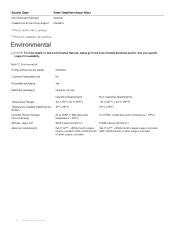
...power supply 80 plus bronze certification 80 plus platinum certification Customer replaceable unit Recyclable packaging MultiPack packaging Optional 260 W EPA bronze 260 W EPA bronze No Yes Optional, US only System specifications 17 See your specific region for availability. Cable Cover Chassis Intrusion Switch Dell... Smartcard Keyboard Chassis lock slot and loop support Tower/ Small form factor/ Micro Optional Optional /Optional /Standard Optional Standard Environmental NOTE: For more details on Dell environmental features, please go to the...
...power supply 80 plus bronze certification 80 plus platinum certification Customer replaceable unit Recyclable packaging MultiPack packaging Optional 260 W EPA bronze 260 W EPA bronze No Yes Optional, US only System specifications 17 See your specific region for availability. Cable Cover Chassis Intrusion Switch Dell... Smartcard Keyboard Chassis lock slot and loop support Tower/ Small form factor/ Micro Optional Optional /Optional /Standard Optional Standard Environmental NOTE: For more details on Dell environmental features, please go to the...
Tower Setup and specifications guide
Page 25
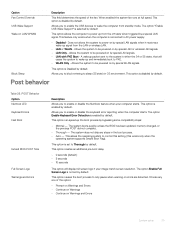
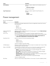
... you to block entering to control this setting (this works only when the operating system supports Simple Boot Flag). Allows the system to be powered on by default. Allows the system to Thorough by default. This option is disabled by special LAN signals. • LAN with PXE Boot... when the computer starts. This option can speed up from standby mode. When enabled the system fan runs at full speed. Allows you to AC power supply. • Disabled - A wakeup packet sent to the system in the boot process. • Auto - The option Enable Full Screen Logo is disabled...
... you to block entering to control this setting (this works only when the operating system supports Simple Boot Flag). Allows the system to be powered on by default. Allows the system to Thorough by default. This option is disabled by special LAN signals. • LAN with PXE Boot... when the computer starts. This option can speed up from standby mode. When enabled the system fan runs at full speed. Allows you to AC power supply. • Disabled - A wakeup packet sent to the system in the boot process. • Auto - The option Enable Full Screen Logo is disabled...
Micro Setup and specifications guide
Page 3
......11 Chipset...12 Storage combinations...12 Audio...13 Video...13 Communications...14 Ports and connectors...14 System board connectors...14 Power supply...15 Physical system dimensions...15 Security...15 Environmental...16 4 System setup...17 System setup...17 General options...18 System...information...18 Video screen options...19 Security...20 Secure boot options...21 Intel Software Guard Extensions options...22 Performance...22 Power management...23 Post behavior...24 Manageability...24 Virtualization support...24 Wireless options...25 Maintenance...25 System logs...26 Advanced configuration...
......11 Chipset...12 Storage combinations...12 Audio...13 Video...13 Communications...14 Ports and connectors...14 System board connectors...14 Power supply...15 Physical system dimensions...15 Security...15 Environmental...16 4 System setup...17 System setup...17 General options...18 System...information...18 Video screen options...19 Security...20 Secure boot options...21 Intel Software Guard Extensions options...22 Performance...22 Power management...23 Post behavior...24 Manageability...24 Virtualization support...24 Wireless options...25 Maintenance...25 System logs...26 Advanced configuration...

Micro Setup and specifications guide
Page 10
... • Ports and connectors • System board connectors • Power supply • Physical system dimensions • Security • Environmental Processor Global Standard Products (GSP) are a subset of Dell's relationship products that are not a measure of performance. The following ...specifications are only those required by law to Dell customers. Processor availability is available for availability and synchronized transitions...
... • Ports and connectors • System board connectors • Power supply • Physical system dimensions • Security • Environmental Processor Global Standard Products (GSP) are a subset of Dell's relationship products that are not a measure of performance. The following ...specifications are only those required by law to Dell customers. Processor availability is available for availability and synchronized transitions...
Micro Setup and specifications guide
Page 15
... 12. Physical system dimensions Chassis volume (liters) Chassis weight (pounds / kilograms) 1.17 2.82 / 1.27 Table 14. Power supply Input Voltage Input current (maximum) 100-240 V, 3.2 A, 50-60 Hz • 90 W PSU (EPS Level V) Physical system dimensions Table 13. Chassis dimensions Height (inches / centimeters) ...
... 12. Physical system dimensions Chassis volume (liters) Chassis weight (pounds / kilograms) 1.17 2.82 / 1.27 Table 14. Power supply Input Voltage Input current (maximum) 100-240 V, 3.2 A, 50-60 Hz • 90 W PSU (EPS Level V) Physical system dimensions Table 13. Chassis dimensions Height (inches / centimeters) ...
Micro Setup and specifications guide
Page 16
... ft.) ISA-71 G1**: Environmental Energy efficient power supply Standard Customer replaceable unit No Recyclable packaging Yes MultiPack packaging Optional, US only Temperature Ranges Temperature Gradient Maximum per 60 Min Humidity Percent Ranges Noncondensing Altitude- See your specific region for availability. Table 17. Security Types Dell Smartcard Keyboard Chassis lock slot and loop...
... ft.) ISA-71 G1**: Environmental Energy efficient power supply Standard Customer replaceable unit No Recyclable packaging Yes MultiPack packaging Optional, US only Temperature Ranges Temperature Gradient Maximum per 60 Min Humidity Percent Ranges Noncondensing Altitude- See your specific region for availability. Table 17. Security Types Dell Smartcard Keyboard Chassis lock slot and loop...
Micro Setup and specifications guide
Page 23
...controls when Deep Sleep is enabled. • Disabled • Enabled in S5 only • Enabled in S4 and S5 This option is connected to AC power supply. • Disabled - Allows you to enable the USB devices to wake the computer from the off your computer using the switch on.... Allows the system to disabled. Sets time to PXE. • WLAN Only - Change the startup time by default This option allows the computer to power up and immediately boot to automatically turn off state when triggered by special WLAN signals. NOTE: This feature does not work if you to block...
...controls when Deep Sleep is enabled. • Disabled • Enabled in S5 only • Enabled in S4 and S5 This option is connected to AC power supply. • Disabled - Allows you to enable the USB devices to wake the computer from the off your computer using the switch on.... Allows the system to disabled. Sets time to PXE. • WLAN Only - Change the startup time by default This option allows the computer to power up and immediately boot to automatically turn off state when triggered by special WLAN signals. NOTE: This feature does not work if you to block...
Small Form Factor Setup and specifications guide
Page 3
...Storage...11 Chipset...12 Storage combinations...12 Audio...12 Video...13 Communications...13 Ports and connectors...14 System board connectors...14 Power supply...14 Physical system dimensions...15 Security...15 Environmental...15 4 System setup...17 System setup...17 General options...17 System ...information...18 Video screen options...19 Security...20 Secure boot options...21 Intel Software Guard Extensions options...21 Performance...22 Power management...22 Post behavior...23 Virtualization support...24 Wireless options...24 Maintenance...24 System logs...25 Advanced configuration...25 5 ...
...Storage...11 Chipset...12 Storage combinations...12 Audio...12 Video...13 Communications...13 Ports and connectors...14 System board connectors...14 Power supply...14 Physical system dimensions...15 Security...15 Environmental...15 4 System setup...17 System setup...17 General options...17 System ...information...18 Video screen options...19 Security...20 Secure boot options...21 Intel Software Guard Extensions options...21 Performance...22 Power management...22 Post behavior...23 Virtualization support...24 Wireless options...24 Maintenance...24 System logs...25 Advanced configuration...25 5 ...


