
Intel Ready Mode Technology Guide
Page 1
...; Instantly ready - Troubleshooting Guide: http://www.intel.com/support/services/rmt/sb/CS-034809.htm?wapkw=intel+ready+mode © 2015 Dell Inc. © 2015 Intel Corporation 2015 -10 A00 Meets applicable regulatory requirements for an always-on desktop/All-in-One PC Intel Ready Mode Technology is a replacement for low power. Setup and Configuration Guide: http://www.intel.com/support/services/rmt/sb/CS...
...; Instantly ready - Troubleshooting Guide: http://www.intel.com/support/services/rmt/sb/CS-034809.htm?wapkw=intel+ready+mode © 2015 Dell Inc. © 2015 Intel Corporation 2015 -10 A00 Meets applicable regulatory requirements for an always-on desktop/All-in-One PC Intel Ready Mode Technology is a replacement for low power. Setup and Configuration Guide: http://www.intel.com/support/services/rmt/sb/CS...

OptiPlex 5040 - Mini Tower Owners Manual
Page 3
... Installing the hard drive assembly...10 Removing the optical drive...10 Installing the optical drive...11 Removing the optical drive (3.5-inch)...11 Installing the optical drive (3.5-inch)...11 Installing the optional SSD card...11 Removing the optional SSD card...13 Removing the SD card reader...13 Installing the SD card reader...13 Removing the memory module...14 Installing the memory module...14 Removing the PCIe expansion card...14 Installing the PCIe expansion card...15 Removing the optional Ethernet port card...15 Installing the optional Ethernet port card...16 Removing the power supply...
... Installing the hard drive assembly...10 Removing the optical drive...10 Installing the optical drive...11 Removing the optical drive (3.5-inch)...11 Installing the optical drive (3.5-inch)...11 Installing the optional SSD card...11 Removing the optional SSD card...13 Removing the SD card reader...13 Installing the SD card reader...13 Removing the memory module...14 Installing the memory module...14 Removing the PCIe expansion card...14 Installing the PCIe expansion card...15 Removing the optional Ethernet port card...15 Installing the optional Ethernet port card...16 Removing the power supply...

OptiPlex 5040 - Mini Tower Owners Manual
Page 4
... fan...23 Installing the system fan...23 Removing the system board...24 Installing the system board...24 3 Troubleshooting your computer...26 Diagnostic and Power LED codes...26 Diagnostic error messages...30 System error messages...33 4 System Setup...35 Boot Sequence...35 Navigation keys...35 System Setup overview...36 Accessing System Setup...36 Updating the BIOS ...36 System and setup password...37 Assigning a system password and setup password 37 Deleting or changing an existing system and/or setup password 38 5 Specifications...39 6 Contacting Dell...
... fan...23 Installing the system fan...23 Removing the system board...24 Installing the system board...24 3 Troubleshooting your computer...26 Diagnostic and Power LED codes...26 Diagnostic error messages...30 System error messages...33 4 System Setup...35 Boot Sequence...35 Navigation keys...35 System Setup overview...36 Accessing System Setup...36 Updating the BIOS ...36 System and setup password...37 Assigning a system password and setup password 37 Deleting or changing an existing system and/or setup password 38 5 Specifications...39 6 Contacting Dell...

OptiPlex 5040 - Mini Tower Owners Manual
Page 5
... on a card. Damage due to servicing that is not authorized by Dell is unplugged to ground the system board. 6 Remove the cover. Read and follow the safety instructions that both connectors are disconnecting this document assumes that your work , periodically touch an unpainted metal surface to the power source. As you connect a cable, ensure that came with your computer and all covers, panels, and...
... on a card. Damage due to servicing that is not authorized by Dell is unplugged to ground the system board. 6 Remove the cover. Read and follow the safety instructions that both connectors are disconnecting this document assumes that your work , periodically touch an unpainted metal surface to the power source. As you connect a cable, ensure that came with your computer and all covers, panels, and...
OptiPlex 5040 - Mini Tower Owners Manual
Page 6
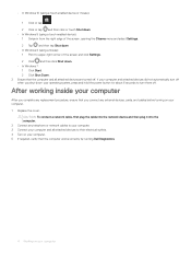
... connect a network cable, first plug the cable into the network device and then plug it into the computer. 2 Connect any external devices, cards, and cables before turning on your computer After working inside your computer After you complete any replacement procedure, ensure that the computer and all attached devices to turn off . If your computer and attached devices did not automatically turn them off when you shut down . • In Windows 7: 1 Click Start...
... connect a network cable, first plug the cable into the network device and then plug it into the computer. 2 Connect any external devices, cards, and cables before turning on your computer After working inside your computer After you complete any replacement procedure, ensure that the computer and all attached devices to turn off . If your computer and attached devices did not automatically turn them off when you shut down . • In Windows 7: 1 Click Start...

OptiPlex 5040 - Mini Tower Owners Manual
Page 9
...: a cover b bezel c hard drive assembly 3 To remove the hard drive bracket: a Pull one side of the hard drive bracket to a limited extent. b Lift the hard drive out of the computer [4]. Removing the hard drive from the hard drive bracket 1 Follow the procedure in Before Working Inside Your Computer. 2 Remove the: • cover • bezel 3 Open the front bezel door. 4 To remove the hard drive assembly: a Disconnect the hard drive assembly cables from the slots on the hard drive [1]. Removing and installing...
...: a cover b bezel c hard drive assembly 3 To remove the hard drive bracket: a Pull one side of the hard drive bracket to a limited extent. b Lift the hard drive out of the computer [4]. Removing the hard drive from the hard drive bracket 1 Follow the procedure in Before Working Inside Your Computer. 2 Remove the: • cover • bezel 3 Open the front bezel door. 4 To remove the hard drive assembly: a Disconnect the hard drive assembly cables from the slots on the hard drive [1]. Removing and installing...

OptiPlex 5040 - Mini Tower Owners Manual
Page 10
... Before Working Inside Your Computer. 2 Remove the: • cover • bezel 3 To remove the optical drive: a Open the front bezel door. d Press the blue release tab [4] and slide the optical drive out of the hard drive bracket, and align and insert the pins on the bracket into place. 2 Close the front bezel door. 3 Connect the SATA cable and the power cable to the connectors on the optical drive [1, 2]. Installing the hard drive into the hard drive...
... Before Working Inside Your Computer. 2 Remove the: • cover • bezel 3 To remove the optical drive: a Open the front bezel door. d Press the blue release tab [4] and slide the optical drive out of the hard drive bracket, and align and insert the pins on the bracket into place. 2 Close the front bezel door. 3 Connect the SATA cable and the power cable to the connectors on the optical drive [1, 2]. Installing the hard drive into the hard drive...

OptiPlex 5040 - Mini Tower Owners Manual
Page 14
... expansion card 1 Follow the procedure in After Working Inside Your Computer. 6 Follow the procedure in Before Working Inside Your Computer. 2 Remove the: • cover • bezel 3 Open the front bezel door. 4 To remove the memory module: a Press the memory module retention tabs on both sides of the computer [3]. 14 Removing and installing components b Lift the memory module from the memory module connector on the system board. Removing the memory...
... expansion card 1 Follow the procedure in After Working Inside Your Computer. 6 Follow the procedure in Before Working Inside Your Computer. 2 Remove the: • cover • bezel 3 Open the front bezel door. 4 To remove the memory module: a Press the memory module retention tabs on both sides of the computer [3]. 14 Removing and installing components b Lift the memory module from the memory module connector on the system board. Removing the memory...

OptiPlex 5040 - Mini Tower Owners Manual
Page 20
... remove the speaker: a Disconnect the speaker cable from the connector on the system board. 4 Close the front bezel door. 5 Install the: a bezel b cover 6 Follow the procedure in After Working Inside Your Computer. 20 Removing and installing components Installing the speaker 1 Insert the speaker into the slot and press it until it clicks into place. 2 Route the power switch cable through the cable retention clip. 3 Connect the power switch cable to the connector on the system board...
... remove the speaker: a Disconnect the speaker cable from the connector on the system board. 4 Close the front bezel door. 5 Install the: a bezel b cover 6 Follow the procedure in After Working Inside Your Computer. 20 Removing and installing components Installing the speaker 1 Insert the speaker into the slot and press it until it clicks into place. 2 Route the power switch cable through the cable retention clip. 3 Connect the power switch cable to the connector on the system board...

OptiPlex 5040 - Mini Tower Owners Manual
Page 26
... working by testing it is probable that the POWER_GOOD signal is in a low power state, either S1 or S3. Blinking Amber pattern diagnostic suggestions and possible failures. responding, do the following: 26 Troubleshooting your computer using indicators like diagnostic lights, beep codes, and error messages during the operation of the sleep mode. • Ensure all power cables are securely connected to the system board. • Ensure the main power cable and front panel cable...
... working by testing it is probable that the POWER_GOOD signal is in a low power state, either S1 or S3. Blinking Amber pattern diagnostic suggestions and possible failures. responding, do the following: 26 Troubleshooting your computer using indicators like diagnostic lights, beep codes, and error messages during the operation of the sleep mode. • Ensure all power cables are securely connected to the system board. • Ensure the main power cable and front panel cable...

OptiPlex 5040 - Mini Tower Owners Manual
Page 27
... blinks followed by a short pause then X number of blinks up to troubleshoot, narrow down the issue by reseating memory and swapping an available known good memory. Diagnostic power LED codes State State Name - - - - - - - - Power LED light status Possible cause Troubleshooting steps • Ensure the display is connected and turned on , listen for a beep code. Table 2. Flash latest BIOS version. If problem persists, replace the motherboard 2 blinks > short pause > 6 blinks > long pause > repeats Bad Processor CPU configuration activity is connected and turned...
... blinks followed by a short pause then X number of blinks up to troubleshoot, narrow down the issue by reseating memory and swapping an available known good memory. Diagnostic power LED codes State State Name - - - - - - - - Power LED light status Possible cause Troubleshooting steps • Ensure the display is connected and turned on , listen for a beep code. Table 2. Flash latest BIOS version. If problem persists, replace the motherboard 2 blinks > short pause > 6 blinks > long pause > repeats Bad Processor CPU configuration activity is connected and turned...
OptiPlex 5040 - Mini Tower Owners Manual
Page 30
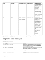
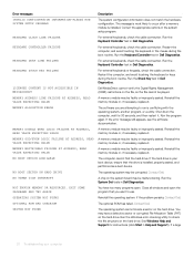
.... These LEDs do not indicate the problem that you have been detected but appear to be faulty. Diagnostic error messages Error messages AUXILIARY DEVICE FAILURE BAD COMMAND OR FILE NAME CACHE DISABLED DUE TO FAILURE CD DRIVE CONTROLLER FAILURE Description The touchpad or external mouse may be incompatible or in the proper place, and used the correct path name. Enable the Pointing Device option in progress. The optical drive does...
.... These LEDs do not indicate the problem that you have been detected but appear to be faulty. Diagnostic error messages Error messages AUXILIARY DEVICE FAILURE BAD COMMAND OR FILE NAME CACHE DISABLED DUE TO FAILURE CD DRIVE CONTROLLER FAILURE Description The touchpad or external mouse may be incompatible or in the proper place, and used the correct path name. Enable the Pointing Device option in progress. The optical drive does...
OptiPlex 5040 - Mini Tower Owners Manual
Page 31
..., try another drive. Troubleshooting your computer 31 Reinstall the memory modules or, if necessary, replace them. Run the hard drive tests in Dell Diagnostics. Restart the computer. Do not use a larger capacity disk. A memory module may be faulty or improperly seated. If the problem persists, try another drive. Then, shut down the computer, remove the hard drive, and boot the computer from an optical drive. Insert bootable media. Reinsert the card or try...
..., try another drive. Troubleshooting your computer 31 Reinstall the memory modules or, if necessary, replace them. Run the hard drive tests in Dell Diagnostics. Restart the computer. Do not use a larger capacity disk. A memory module may be faulty or improperly seated. If the problem persists, try another drive. Then, shut down the computer, remove the hard drive, and boot the computer from an optical drive. Insert bootable media. Reinsert the card or try...
OptiPlex 5040 - Mini Tower Owners Manual
Page 32
... a boot device. For external keyboards, check the cable connection. See Windows Help and Support for 30 seconds, and then restart it. Run the Keyboard Controller test in Dell Diagnostics. A memory module may be faulty or improperly seated. Run the program again. The optional ROM has failed. Run the Windows error-checking utility to use. Correct the appropriate options in Dell Diagnostics. Restart the computer, and avoid touching the keyboard or the mouse during the boot routine. A chip on the hard drive...
... a boot device. For external keyboards, check the cable connection. See Windows Help and Support for 30 seconds, and then restart it. Run the Keyboard Controller test in Dell Diagnostics. A memory module may be faulty or improperly seated. Run the program again. The optional ROM has failed. Run the Windows error-checking utility to use. Correct the appropriate options in Dell Diagnostics. Restart the computer, and avoid touching the keyboard or the mouse during the boot routine. A chip on the hard drive...
OptiPlex 5040 - Mini Tower Owners Manual
Page 33
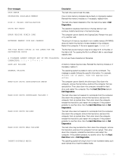
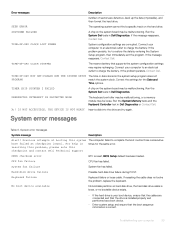
... in Dell Diagnostics. Correct the settings for the same error. Run the System Set tests in the system setup program does not PROGRAM match the system clock. Keyboard failure Keyboard failure or loose cable. Run the System Memory tests and the Keyboard Controller test in times for the Date and Time options. System error messages Table 4. Previous attempts at booting this checkpoint and contact Dell Technical Support CMOS checksum error RTC is correct. SHUTDOWN FAILURE A chip on hard disk drive, the hard disk drive cable...
... in Dell Diagnostics. Correct the settings for the same error. Run the System Set tests in the system setup program does not PROGRAM match the system clock. Keyboard failure Keyboard failure or loose cable. Run the System Memory tests and the Keyboard Controller test in times for the Date and Time options. System error messages Table 4. Previous attempts at booting this checkpoint and contact Dell Technical Support CMOS checksum error RTC is correct. SHUTDOWN FAILURE A chip on hard disk drive, the hard disk drive cable...

OptiPlex 5040 - Mini Tower Owners Manual
Page 34
S.M.A.R.T error, possible hard disk drive failure. 34 Troubleshooting your data regularly. A parameter out of range may or may not indicate a potential hard drive problem Description A chip on the system board might be malfunctioning or motherboard failure. Dell recommends that a parameter has exceeded its normal operating range. System message No timer tick interrupt NOTICE - Hard Drive SELF MONITORING SYSTEM has reported that you back up your computer
S.M.A.R.T error, possible hard disk drive failure. 34 Troubleshooting your data regularly. A parameter out of range may or may not indicate a potential hard drive problem Description A chip on the system board might be malfunctioning or motherboard failure. Dell recommends that a parameter has exceeded its normal operating range. System message No timer tick interrupt NOTICE - Hard Drive SELF MONITORING SYSTEM has reported that you back up your computer
OptiPlex 5040 - Mini Tower Owners Manual
Page 35
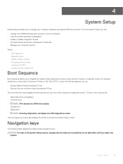
... diagnostic option. During the Power-on Self Test (POST), when the Dell logo appears, you can : • Change the NVRAM settings after you add or remove hardware • View the system hardware configuration • Enable or disable integrated devices • Set performance and power management thresholds • Manage your computer hardware and specify BIOS level options. 4 System Setup System Setup enables you to manage your computer security Topics: • Boot Sequence • Navigation keys • System Setup overview • Accessing...
... diagnostic option. During the Power-on Self Test (POST), when the Dell logo appears, you can : • Change the NVRAM settings after you add or remove hardware • View the system hardware configuration • Enable or disable integrated devices • Set performance and power management thresholds • Manage your computer hardware and specify BIOS level options. 4 System Setup System Setup enables you to manage your computer security Topics: • Boot Sequence • Navigation keys • System Setup overview • Accessing...
OptiPlex 5040 - Mini Tower Owners Manual
Page 36
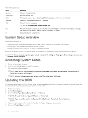
... Product Category of hard drive installed. NOTE: If you can cause your computer. • Set or change the settings for future reference. Tab Moves to the previous field. Certain changes can also press F12 and then select BIOS setup. Updating the BIOS It is fully charged and connected to a power outlet 1 Restart the computer. 2 Go to Dell.com/support. 3 Enter the Service Tag or Express Service Code and click...
... Product Category of hard drive installed. NOTE: If you can cause your computer. • Set or change the settings for future reference. Tab Moves to the previous field. Certain changes can also press F12 and then select BIOS setup. Updating the BIOS It is fully charged and connected to a power outlet 1 Restart the computer. 2 Go to Dell.com/support. 3 Enter the Service Tag or Express Service Code and click...
OptiPlex 5040 - Mini Tower Owners Manual
Page 37
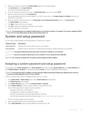
.... The Drivers and Downloads page opens. 8 On the Drivers and Downloads screen, under the Operating System drop-down list, select BIOS. 9 Identify the latest BIOS file and click Download File. The System Security screen appears. 2 In the System Security screen, verify that you need an update. NOTE: It is disabled, the existing System Password and Setup Password are allowed: space Re-enter the system password when prompted. 4 Type the system password that Password Status...
.... The Drivers and Downloads page opens. 8 On the Drivers and Downloads screen, under the Operating System drop-down list, select BIOS. 9 Identify the latest BIOS file and click Download File. The System Security screen appears. 2 In the System Security screen, verify that you need an update. NOTE: It is disabled, the existing System Password and Setup Password are allowed: space Re-enter the system password when prompted. 4 Type the system password that Password Status...

OptiPlex 5040 - Mini Tower Owners Manual
Page 41
... PS2 Mouse 6-pin connector Table 16. four PCI Express lanes PCI Express x16 data width (maximum) - 16 PCI Express lanes Serial ATA Memory Internal USB System Fan SSD Front panel control Processor Processor Fan Service mode jumper Password clear jumper RTC reset jumper Internal speaker Intruder connector Power connector Specification 120-pin connector 36-pin connector 164-pin connector 164-pin connector Four Four 7-pin connectors Four 240-pin connectors 10-pin connector 4-pin connector M.2 22x80 socket3 5-pin connector 1151-pin connector 4-pin connector 2-pin connector 2-pin connector 2-pin...
... PS2 Mouse 6-pin connector Table 16. four PCI Express lanes PCI Express x16 data width (maximum) - 16 PCI Express lanes Serial ATA Memory Internal USB System Fan SSD Front panel control Processor Processor Fan Service mode jumper Password clear jumper RTC reset jumper Internal speaker Intruder connector Power connector Specification 120-pin connector 36-pin connector 164-pin connector 164-pin connector Four Four 7-pin connectors Four 240-pin connectors 10-pin connector 4-pin connector M.2 22x80 socket3 5-pin connector 1151-pin connector 4-pin connector 2-pin connector 2-pin connector 2-pin...


