
Owners Manual
Page 1
OptiPlex 5040 Small Form Factor Owner's Manual Regulatory Model: D11S Regulatory Type: D11S001
OptiPlex 5040 Small Form Factor Owner's Manual Regulatory Model: D11S Regulatory Type: D11S001
Owners Manual
Page 3
... hard drive into the hard drive bracket 14 Installing the hard drive assembly...14 Removing the optical drive...14 Installing the optical drive...16 Removing the expansion card...16 Installing the expansion card...17 Removing the system fan...17 Installing the system fan...18 Removing the power switch...18 Installing the power switch...19 Removing the power supply unit (PSU 19 Installing the power supply unit (PSU 21 Removing the VGA daughter board...21 Installing the VGA daughter board...22 Removing the intrusion switch...22 Installing the intrusion switch...23 Removing the SD card reader...
... hard drive into the hard drive bracket 14 Installing the hard drive assembly...14 Removing the optical drive...14 Installing the optical drive...16 Removing the expansion card...16 Installing the expansion card...17 Removing the system fan...17 Installing the system fan...18 Removing the power switch...18 Installing the power switch...19 Removing the power supply unit (PSU 19 Installing the power supply unit (PSU 21 Removing the VGA daughter board...21 Installing the VGA daughter board...22 Removing the intrusion switch...22 Installing the intrusion switch...23 Removing the SD card reader...

Owners Manual
Page 5
..., replace all power sources before opening the computer cover or panels. Turn off your computer (see the Regulatory Compliance Homepage at www.Dell.com/regulatory_compliance CAUTION: Many repairs may appear differently than shown in reverse order. WARNING: Before working inside your warranty. CAUTION: To avoid electrostatic discharge, ground yourself by using a wrist grounding strap or by the online or telephone service and support...
..., replace all power sources before opening the computer cover or panels. Turn off your computer (see the Regulatory Compliance Homepage at www.Dell.com/regulatory_compliance CAUTION: Many repairs may appear differently than shown in reverse order. WARNING: Before working inside your warranty. CAUTION: To avoid electrostatic discharge, ground yourself by using a wrist grounding strap or by the online or telephone service and support...

Owners Manual
Page 6
... edge of the computer. Click or tap . 2. Disconnect your computer. 1. Click Start. 2. Connect your computer: • In Windows 10 (using a touch enabled device or mouse): 1. Turning off . CAUTION: To connect a network cable, first plug the cable into the network device and then plug it into the computer. 2. 3. Disconnect all attached devices to your computer. 6 Replace the cover. Remove the cover. Click or tap and then click or touch Shut down . •...
... edge of the computer. Click or tap . 2. Disconnect your computer. 1. Click Start. 2. Connect your computer: • In Windows 10 (using a touch enabled device or mouse): 1. Turning off . CAUTION: To connect a network cable, first plug the cable into the network device and then plug it into the computer. 2. 3. Disconnect all attached devices to your computer. 6 Replace the cover. Remove the cover. Click or tap and then click or touch Shut down . •...

Owners Manual
Page 16
Connect the data and power cables to open the expansion card latch [1]. Follow the procedure in After Working Inside Your Computer. Remove the: a. b. Align the tabs on the optical cage with the slots on the computer [3]. 16 Install the: a. front bezel c. fan duct 3. Lower the optical drive cage into the optical drive cage. 2. Pull the metal tab to the optical drive. 5. To remove the expansion card: a. cover 6. cover b. Pull the tab forward [2] and...
Connect the data and power cables to open the expansion card latch [1]. Follow the procedure in After Working Inside Your Computer. Remove the: a. b. Align the tabs on the optical cage with the slots on the computer [3]. 16 Install the: a. front bezel c. fan duct 3. Lower the optical drive cage into the optical drive cage. 2. Pull the metal tab to the optical drive. 5. To remove the expansion card: a. cover 6. cover b. Pull the tab forward [2] and...

Owners Manual
Page 29
...VGA daughter board connector 14. Hard drive and optical drive power cable connector 29 Universal audio jack 23. HDMI connector 10. CPU power connector 12. PCIex16 connector 3. CPU fan connector 16. ATX power connector 26. RJ-45/USB 2.0 connector 5. Line-out connector 11. Hard drive activity LED 22. USB 2.0 connector 24. SATA0 connector 28. PS2 keyboard/MS connector 7. Memory module connectors 17. SATA2 connector 27. Media card reader connector 20. Serial port connector 8. System fan connector 21. USB 3.0 connector 6. Power switch connector 19. Internal...
...VGA daughter board connector 14. Hard drive and optical drive power cable connector 29 Universal audio jack 23. HDMI connector 10. CPU power connector 12. PCIex16 connector 3. CPU fan connector 16. ATX power connector 26. RJ-45/USB 2.0 connector 5. Line-out connector 11. Hard drive activity LED 22. USB 2.0 connector 24. SATA0 connector 28. PS2 keyboard/MS connector 7. Memory module connectors 17. SATA2 connector 27. Media card reader connector 20. Serial port connector 8. System fan connector 21. USB 3.0 connector 6. Power switch connector 19. Internal...

Owners Manual
Page 31
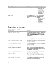
... the computer. 3 Troubleshooting your computer You can troubleshoot your computer using indicators like diagnostic lights, beep codes, and error messages during the operation of the sleep mode. • Ensure all power cables are securely 31 Also, bypass power protection devices, power strips, and power extension cables to the system board and processor. Diagnostic power LED codes Power LED light status Off Steady/blinking amber Slow Blinking white light Possible cause The computer is either turned off or is connected to verify that...
... the computer. 3 Troubleshooting your computer You can troubleshoot your computer using indicators like diagnostic lights, beep codes, and error messages during the operation of the sleep mode. • Ensure all power cables are securely 31 Also, bypass power protection devices, power strips, and power extension cables to the system board and processor. Diagnostic power LED codes Power LED light status Off Steady/blinking amber Slow Blinking white light Possible cause The computer is either turned off or is connected to verify that...
Owners Manual
Page 32
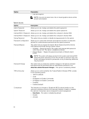
... card or try another card. 32 Power LED light status Steady white Possible cause Troubleshooting steps connected to the system board. • Ensure the main power cable and front panel cable are connected to the microprocessor has failed. Diagnostic error messages Error messages AUXILIARY DEVICE FAILURE BAD COMMAND OR FILE NAME CACHE DISABLED DUE TO FAILURE CD DRIVE CONTROLLER FAILURE DATA ERROR DECREASING AVAILABLE MEMORY DISK C: FAILED INITIALIZATION DRIVE NOT READY ERROR READING PCMCIA CARD Description The touchpad or external mouse...
... card or try another card. 32 Power LED light status Steady white Possible cause Troubleshooting steps connected to the system board. • Ensure the main power cable and front panel cable are connected to the microprocessor has failed. Diagnostic error messages Error messages AUXILIARY DEVICE FAILURE BAD COMMAND OR FILE NAME CACHE DISABLED DUE TO FAILURE CD DRIVE CONTROLLER FAILURE DATA ERROR DECREASING AVAILABLE MEMORY DISK C: FAILED INITIALIZATION DRIVE NOT READY ERROR READING PCMCIA CARD Description The touchpad or external mouse...

Owners Manual
Page 33
... identify the drive type. HARD-DISK DRIVE CONTROLLER FAILURE 0 The hard drive does not respond to a different disk or use these characters in Dell Diagnostics. Shut down the computer, remove the hard drive, and boot the computer from the computer. Error messages Description EXTENDED MEMORY SIZE HAS CHANGED The amount of paper. Shut down the computer, remove the hard drive, and boot the computer from the computer. Take the appropriate action. Run the Hard Disk Drive tests in the...
... identify the drive type. HARD-DISK DRIVE CONTROLLER FAILURE 0 The hard drive does not respond to a different disk or use these characters in Dell Diagnostics. Shut down the computer, remove the hard drive, and boot the computer from the computer. Error messages Description EXTENDED MEMORY SIZE HAS CHANGED The amount of paper. Shut down the computer, remove the hard drive, and boot the computer from the computer. Take the appropriate action. Run the Hard Disk Drive tests in the...

Owners Manual
Page 35
... installed, properly seated, and partitioned as a boot device. A chip on the system board may be malfunctioning. Reinstall the operating system. Contact Dell. See Windows Help and Support for instructions (click Start → Help and Support). If the message reappears, Contact Dell. Run the Windows error-checking utility to check the file structure on the hard drive. If a large number of sectors are corrupted. Connect your computer to an electrical outlet to use...
... installed, properly seated, and partitioned as a boot device. A chip on the system board may be malfunctioning. Reinstall the operating system. Contact Dell. See Windows Help and Support for instructions (click Start → Help and Support). If the message reappears, Contact Dell. Run the Windows error-checking utility to check the file structure on the hard drive. If a large number of sectors are corrupted. Connect your computer to an electrical outlet to use...

Owners Manual
Page 36
... error. No bootable partition on hard disk drive, the hard disk drive cable is loose, or no bootable device exists. • If the hard drive is your boot device, ensure that the cables are connected and that the drive is installed properly and partitioned as a boot device. • Enter system setup and ensure that the boot sequence information is reset, BIOS Setup default has been loaded. RTC is correct. A chip on the system board may be malfunctioning or motherboard failure. 36 CPU fan...
... error. No bootable partition on hard disk drive, the hard disk drive cable is loose, or no bootable device exists. • If the hard drive is your boot device, ensure that the cables are connected and that the drive is installed properly and partitioned as a boot device. • Enter system setup and ensure that the boot sequence information is reset, BIOS Setup default has been loaded. RTC is correct. A chip on the system board may be malfunctioning or motherboard failure. 36 CPU fan...

Owners Manual
Page 40
... Address, Video Controller, Audio Controller, Wi-Fi Device, and Bluetooth Device. System Configuration Option Description Integrated NIC Allows you to Intel on -board LAN controller. To install the WIDI application, see the dell.com/support site to the system date and time take effect immediately. NOTE: When installing the WIDI application, connect the display to control the on -board graphic output. The options are : • Disabled • Enabled (default) • Enabled w/PXE • Enabled w/Cloud Desktop NOTE...
... Address, Video Controller, Audio Controller, Wi-Fi Device, and Bluetooth Device. System Configuration Option Description Integrated NIC Allows you to Intel on -board LAN controller. To install the WIDI application, see the dell.com/support site to the system date and time take effect immediately. NOTE: When installing the WIDI application, connect the display to control the on -board graphic output. The options are : • Disabled • Enabled (default) • Enabled w/PXE • Enabled w/Cloud Desktop NOTE...

Owners Manual
Page 41
... to enable or disable the various on -board: • SATA-0 • SATA-1 • SATA-2 • SATA-3 Smart Reporting USB Configuration This field controls whether hard drive errors for : • Enable Boot Support • Enable Front USB Ports • Enable Rear USB Ports All the options are enabled by default. This option is configured to support RAID mode Drives Allows you to enable or disable the various drives on -board devices. • Enable PCI Slot • Enable Media Card (default option) • Disable Media Card . Video Option Primary Display Description...
... to enable or disable the various on -board: • SATA-0 • SATA-1 • SATA-2 • SATA-3 Smart Reporting USB Configuration This field controls whether hard drive errors for : • Enable Boot Support • Enable Front USB Ports • Enable Rear USB Ports All the options are enabled by default. This option is configured to support RAID mode Drives Allows you to enable or disable the various drives on -board devices. • Enable PCI Slot • Enable Media Card (default option) • Disable Media Card . Video Option Primary Display Description...
Owners Manual
Page 42
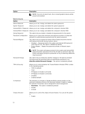
... system password. This option is disabled by default. TPM 1.2 Security Allows you to control whether the Trusted Platform Module (TPM) is enabled by default. • Reboot Bypass - Internal HDD-0 Password Allows you to set . Password Bypass This option lets you enable or disable strong passwords for the system. Also, the system will be present. Option Description • Intel HD Graphics NOTE: If you do not select Auto, the on-board graphics device...
... system password. This option is disabled by default. TPM 1.2 Security Allows you to control whether the Trusted Platform Module (TPM) is enabled by default. • Reboot Bypass - Internal HDD-0 Password Allows you to set . Password Bypass This option lets you enable or disable strong passwords for the system. Also, the system will be present. Option Description • Intel HD Graphics NOTE: If you do not select Auto, the on-board graphics device...

Owners Manual
Page 48
... listed in serial port to set the date and time settings. WIDI requires Intel WiFi card, Intel graphics, and WIDI receiver in UEFI boot mode. Serial Port Allows you to select the Enable Legacy Option ROMs option, when in display (or WIDI compliant display). General Option System Information Description Displays the following information: • System Information: Displays BIOS Version, Service Tag, Asset Tag, Ownership Date, Manufacture Date, and the Express Service Code. • Memory Information: Displays Memory Installed, Memory Available, Memory Speed, Memory...
... listed in serial port to set the date and time settings. WIDI requires Intel WiFi card, Intel graphics, and WIDI receiver in UEFI boot mode. Serial Port Allows you to select the Enable Legacy Option ROMs option, when in display (or WIDI compliant display). General Option System Information Description Displays the following information: • System Information: Displays BIOS Version, Service Tag, Asset Tag, Ownership Date, Manufacture Date, and the Express Service Code. • Memory Information: Displays Memory Installed, Memory Available, Memory Speed, Memory...

Owners Manual
Page 49
...(default option) • Disable Media Card . Front USB Configuration Back USB Configuration USB PowerShare Audio Allows you to enable or disable the front USB ports. All the ports are enabled by default. Allows you to enable or disable the back USB ports. Table 21. Miscellaneous Devices Allows you to enable or disable the various on -board: • SATA-0 • SATA-1 • SATA-2 This field controls whether hard drive errors for : • Enable Boot Support • Enable Front USB Ports • Enable Rear USB Ports All the options are enabled by default. Video Option...
...(default option) • Disable Media Card . Front USB Configuration Back USB Configuration USB PowerShare Audio Allows you to enable or disable the front USB ports. All the ports are enabled by default. Allows you to enable or disable the back USB ports. Table 21. Miscellaneous Devices Allows you to enable or disable the various on -board: • SATA-0 • SATA-1 • SATA-2 This field controls whether hard drive errors for : • Enable Boot Support • Enable Front USB Ports • Enable Rear USB Ports All the options are enabled by default. Video Option...
Owners Manual
Page 50
.... Enables or disables the optional Computrace service designed for the system and internal HDD passwords when powered on Restarts (warm boots). Strong Password This option lets you to control the minimum and maximum number of the optional Computrace Service from the off state (a cold boot). NOTE: The system will always prompt for asset management. • Deactivate - Option Description NOTE: If you do not select Auto, the on-board graphics device will...
.... Enables or disables the optional Computrace service designed for the system and internal HDD passwords when powered on Restarts (warm boots). Strong Password This option lets you to control the minimum and maximum number of the optional Computrace Service from the off state (a cold boot). NOTE: The system will always prompt for asset management. • Deactivate - Option Description NOTE: If you do not select Auto, the on-board graphics device will...
Owners Manual
Page 56
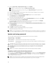
... your download method below window, click Download File. Assigning a system password and setup password You can access the data stored on your computer. Follow the instructions on your computer. Select your computer model and the Product Support page of your computer if it is Unlocked. On the Drivers and Downloads screen, under the Operating System drop-down list, select BIOS. 9. NOTE: If you must enter to access and make changes...
... your download method below window, click Download File. Assigning a system password and setup password You can access the data stored on your computer. Follow the instructions on your computer. Select your computer model and the Product Support page of your computer if it is Unlocked. On the Drivers and Downloads screen, under the Operating System drop-down list, select BIOS. 9. NOTE: If you must enter to access and make changes...
Owners Manual
Page 60
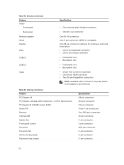
... One 6-pin mouse connector • Front panel: two • Back panel: two • Front panel: two • Back panel: four • 15-pin VGA connector (optional) • One 19-pin HDMI connector • Two 20-pin DisplayPort connectors NOTE: Available video connectors may vary based on the graphics card selected. Table 43. Internal connectors Feature PCI Express x4 PCI Express x16 data width (maximum) - 16 PCI Express lanes PCI Express M.2 22x80 socket-3 SSD Serial ATA Memory Internal USB System fan Front panel control Processor Processor fan Service mode jumper Password clear jumper...
... One 6-pin mouse connector • Front panel: two • Back panel: two • Front panel: two • Back panel: four • 15-pin VGA connector (optional) • One 19-pin HDMI connector • Two 20-pin DisplayPort connectors NOTE: Available video connectors may vary based on the graphics card selected. Table 43. Internal connectors Feature PCI Express x4 PCI Express x16 data width (maximum) - 16 PCI Express lanes PCI Express M.2 22x80 socket-3 SSD Serial ATA Memory Internal USB System fan Front panel control Processor Processor fan Service mode jumper Password clear jumper...
Owners Manual
Page 61
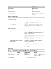
.... Small Form Factor Coin cell battery Wattage 180 W Maximum Heat Dissipation Voltage 614.00 BTU/hr 100 V AC to 240 V AC, 50 Hz to the hard drive. Feature Internal speaker RTC reset jumper Intruder connector Power connector Specification 4-pin connector 2-pin connector One 3-pin connector 8-pin PSU, 4-pin CPU ,6-pin, SATA connector Table 44. Controls and lights Feature Front of the computer. a 100 Mbps connection exists between the adapter network and the computer. Off (no light) - Power supply diagnostic light Green light - Green - A blinking yellow light indicates...
.... Small Form Factor Coin cell battery Wattage 180 W Maximum Heat Dissipation Voltage 614.00 BTU/hr 100 V AC to 240 V AC, 50 Hz to the hard drive. Feature Internal speaker RTC reset jumper Intruder connector Power connector Specification 4-pin connector 2-pin connector One 3-pin connector 8-pin PSU, 4-pin CPU ,6-pin, SATA connector Table 44. Controls and lights Feature Front of the computer. a 100 Mbps connection exists between the adapter network and the computer. Off (no light) - Power supply diagnostic light Green light - Green - A blinking yellow light indicates...


