User Manual
Page 1
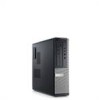
... Of Mini-Tower 1. microphone connector 5. hard-drive activity light 10. diagnostic lights (4) 6. power cable connector Regulatory Model :D12M, D07D, D04S Regulatory Type :D12M001, D07D001, D04S001 2011 - 05 power button 2. optical drive 7. power-supply diagnostic light 11. USB 2.0 connectors (2) 9. power-supply diagnostic button 12. Front And Back View Figure 1. optical drive bay 3. Dell Optiplex 390 Setup And Features Information About Warnings WARNING: A WARNING indicates a potential...
... Of Mini-Tower 1. microphone connector 5. hard-drive activity light 10. diagnostic lights (4) 6. power cable connector Regulatory Model :D12M, D07D, D04S Regulatory Type :D12M001, D07D001, D04S001 2011 - 05 power button 2. optical drive 7. power-supply diagnostic light 11. USB 2.0 connectors (2) 9. power-supply diagnostic button 12. Front And Back View Figure 1. optical drive bay 3. Dell Optiplex 390 Setup And Features Information About Warnings WARNING: A WARNING indicates a potential...
User Manual
Page 2
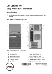
Front And Back View 15. power button 4. hard-drive activity light 8. security cable slot 11. expansion card slots (4) 14. expansion card slots (4) Desktop - optical drive 2. USB 2.0 connectors (2) 5. diagnostic lights (4) 9. back panel connectors 14. padlock ring Figure 2. optical drive eject button 3. power-supply diagnostic button 2 microphone connector 6. power-supply diagnostic light 15. Front And Back View Of Desktop 1. headphone connector 7. power cable connector 12. padlock ring 10. back panel connectors 13. 13. security cable slot 16.
Front And Back View 15. power button 4. hard-drive activity light 8. security cable slot 11. expansion card slots (4) 14. expansion card slots (4) Desktop - optical drive 2. USB 2.0 connectors (2) 5. diagnostic lights (4) 9. back panel connectors 14. padlock ring Figure 2. optical drive eject button 3. power-supply diagnostic button 2 microphone connector 6. power-supply diagnostic light 15. Front And Back View Of Desktop 1. headphone connector 7. power cable connector 12. padlock ring 10. back panel connectors 13. 13. security cable slot 16.
User Manual
Page 4
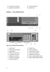
Small Form Factor - USB 2.0 connectors (2) 5. padlock ring 10. back panel connectors 15. Front And Back View Figure 4. power button 4. hard-drive activity light 9. power cable connector 12. optical drive eject button 3. diagnostic lights (4) 8. security cable slot 11. Front And Back View Of Small Form Factor 1. headphone connector 7. optical drive 2. microphone connector 6. power-supply diagnostic light 14. expansion card slots (2) 4 power-supply diagnostic button 13.
Small Form Factor - USB 2.0 connectors (2) 5. padlock ring 10. back panel connectors 15. Front And Back View Figure 4. power button 4. hard-drive activity light 9. power cable connector 12. optical drive eject button 3. diagnostic lights (4) 8. security cable slot 11. Front And Back View Of Small Form Factor 1. headphone connector 7. optical drive 2. microphone connector 6. power-supply diagnostic light 14. expansion card slots (2) 4 power-supply diagnostic button 13.
User Manual
Page 8
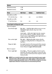
...: Power button light Blue light - When the system power supply voltage is reading data from or writing data to the power connector (at support.dell.com/manuals. Solid blue light indicates power-on and is functional. Blinking amber light indicates a problem with the system board or power supply....system board. Diagnostic lights Four lights located on the diagnostic lights, see the Service Manual at the back of the power system by pressing the power-supply diagnostic button. If the LED does not light up, the power supply may be connected during this test. 8 The power cable must be...
...: Power button light Blue light - When the system power supply voltage is reading data from or writing data to the power connector (at support.dell.com/manuals. Solid blue light indicates power-on and is functional. Blinking amber light indicates a problem with the system board or power supply....system board. Diagnostic lights Four lights located on the diagnostic lights, see the Service Manual at the back of the power system by pressing the power-supply diagnostic button. If the LED does not light up, the power supply may be connected during this test. 8 The power cable must be...
Technical Guide
Page 3
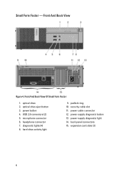
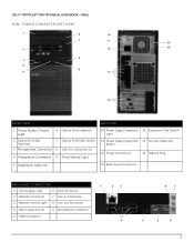
DELL™ OPTIPLEX™ 390 TECHNICAL GUIDEBOOK -FINAL MINI TOWER COMPUTER (MT) VIEW 1 6 10 7 11 15 2 12 16 8 3 4 9 5 13 14 FRONT VIEW BACK VIEW 1 Power Button, Power Light 6 Optical Drive (optional) 2 Optical Drive Bay (optional) 7 Optical Drive Eject Button 3 Microphone Connector 8 USB 2.0 Connectors (2) 4 Headphone Connector 9 Drive Activity Light 10 Power Supply Diagnostic 14 Expansion Card Slots(4) Light 11 Power Supply Diagnostic 15 Security Cable...
DELL™ OPTIPLEX™ 390 TECHNICAL GUIDEBOOK -FINAL MINI TOWER COMPUTER (MT) VIEW 1 6 10 7 11 15 2 12 16 8 3 4 9 5 13 14 FRONT VIEW BACK VIEW 1 Power Button, Power Light 6 Optical Drive (optional) 2 Optical Drive Bay (optional) 7 Optical Drive Eject Button 3 Microphone Connector 8 USB 2.0 Connectors (2) 4 Headphone Connector 9 Drive Activity Light 10 Power Supply Diagnostic 14 Expansion Card Slots(4) Light 11 Power Supply Diagnostic 15 Security Cable...
Technical Guide
Page 5
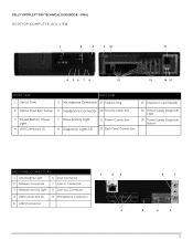
DELL™ OPTIPLEX™ 390 TECHNICAL GUIDEBOOK -FINAL DESKTOP COMPUTER (DT) VIEW 1 2 3 9 10 11 4 56 7 8 12 13 14 15 FRONT VIEW 1 Optical Drive BACK VIEW 5 Microphone Connector 9 Padlock Ring 13 Expansion Card Slots(4) 2 Optical Drive Eject Button 6 Headphone Connector 10 Security Cable Slot 3 Power Button, Power Light 4 USB Connectors (2) 7 Drive Activity Light 8 Diagnostic Lights (4) 11 Power Connectors 12 Back Panel...
DELL™ OPTIPLEX™ 390 TECHNICAL GUIDEBOOK -FINAL DESKTOP COMPUTER (DT) VIEW 1 2 3 9 10 11 4 56 7 8 12 13 14 15 FRONT VIEW 1 Optical Drive BACK VIEW 5 Microphone Connector 9 Padlock Ring 13 Expansion Card Slots(4) 2 Optical Drive Eject Button 6 Headphone Connector 10 Security Cable Slot 3 Power Button, Power Light 4 USB Connectors (2) 7 Drive Activity Light 8 Diagnostic Lights (4) 11 Power Connectors 12 Back Panel...
Technical Guide
Page 7
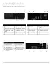
DELL™ OPTIPLEX™ 390 TECHNICAL GUIDEBOOK -FINAL SMALL FORM FACTOR COMPUTER (SFF) VIEW 1 2 3 9 10 11 12 13 4 56 7 8 14 15 FRONT VIEW 1 Optical Drive 5 Microphone Connector 2 Optical Drive Eject Button 6 Headphone Connector 3 Power Button, Power Light 4 USB 2.0 Connectors (2) 7 Diagnostic Lights (4) 8 Drive Activity Light BACK VIEW 9 Padlock Ring 10 Security Cable Slot 11 Power Connectors 13 Power Supply Diagnostic Light 14 Back Panel...
DELL™ OPTIPLEX™ 390 TECHNICAL GUIDEBOOK -FINAL SMALL FORM FACTOR COMPUTER (SFF) VIEW 1 2 3 9 10 11 12 13 4 56 7 8 14 15 FRONT VIEW 1 Optical Drive 5 Microphone Connector 2 Optical Drive Eject Button 6 Headphone Connector 3 Power Button, Power Light 4 USB 2.0 Connectors (2) 7 Diagnostic Lights (4) 8 Drive Activity Light BACK VIEW 9 Padlock Ring 10 Security Cable Slot 11 Power Connectors 13 Power Supply Diagnostic Light 14 Back Panel...
Owners Manual
Page 85
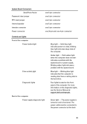
... computer: Power button light Drive activity light Diagnostic lights Back of the computer. Solid blue light indicates power-on the front panel of the computer. Blinking amber light indicates a problem with the system board or power supply. For more information on and is reading data from or writing data to the power connector (at support.dell.com/manuals...
... computer: Power button light Drive activity light Diagnostic lights Back of the computer. Solid blue light indicates power-on the front panel of the computer. Blinking amber light indicates a problem with the system board or power supply. For more information on and is reading data from or writing data to the power connector (at support.dell.com/manuals...


