Dell OptiPlex 390 Support Question
Dell OptiPlex 390 Support Question
Find answers below for this question about Dell OptiPlex 390.Need a Dell OptiPlex 390 manual? We have 3 online manuals for this item!
Question posted by CONbebe on October 1st, 2013
How To Use Dell Optiplex 390 Power Supply Diagnostic Button
The person who posted this question about this Dell product did not include a detailed explanation. Please use the "Request More Information" button to the right if more details would help you to answer this question.
Current Answers
Related Dell OptiPlex 390 Manual Pages
User Manual - Page 1
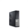
power-supply diagnostic button 12. diagnostic lights (4) 6. USB 2.0 connectors (2) 9. Dell Optiplex 390
Setup And Features Information
About Warnings
WARNING: A WARNING indicates a potential for property damage, personal injury, or death.
power button 2. headphone connector 4. power-supply diagnostic light 11. hard-drive activity light 10. microphone connector 5. optical ...
User Manual - Page 2
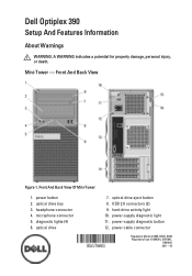
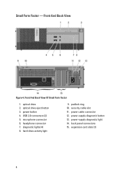
... 7. padlock ring 10. back panel connectors 13. power-supply diagnostic light 15. Front And Back View
15. Front And Back View Of Desktop
1. optical drive 2. optical drive eject button 3. power-supply diagnostic button
2 security cable slot 16. security cable slot 11. power cable connector 12. microphone connector 6. power button 4. expansion card slots (4) 14. hard-drive...
User Manual - Page 4
hard-drive activity light
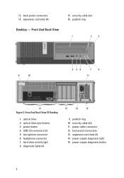
9. power cable connector 12. Small Form Factor - power button 4. diagnostic lights (4) 8. microphone connector 6. power-supply diagnostic light 14. headphone connector 7. padlock ring 10. optical drive 2. optical drive eject button 3. power-supply diagnostic button 13. USB 2.0 connectors (2) 5. expansion card slots (2)
4 back panel ...
User Manual - Page 8
... start, indicates a problem with the system board. Back of the power system by pressing the power-supply diagnostic button. NOTE: You can test the health of computer:
Power supply light
Green light -
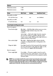
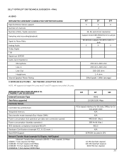
When the system power supply voltage is reading data from or writing data to the power connector (at support.dell.com/manuals. Memory Minimum memory Maximum memory
1 GB 8 GB...
Technical Guide - Page 3
...; OPTIPLEX™ 390 TECHNICAL GUIDEBOOK -FINAL
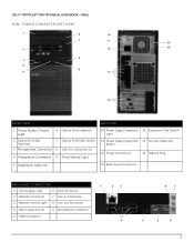
MINI TOWER COMPUTER (MT) VIEW
1
6
10
7
11
15
2
12
16
8 3
4
9
5
13
14
FRONT VIEW
BACK VIEW
1 Power Button, Power Light
6 Optical Drive (optional)
2 Optical Drive Bay (optional)
7 Optical Drive Eject Button
3 Microphone Connector 8 USB 2.0 Connectors (2)
4 Headphone Connector 9 Drive Activity Light
10 Power Supply Diagnostic...
Technical Guide - Page 4
DELL™ OPTIPLEX™ 390 TECHNICAL GUIDEBOOK -FINAL
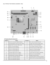
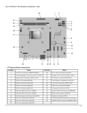
MT System Board Components
Number
Name
1
Front IO connector (FRONTPANEL))
...16x Connector (SLOT1) System fan Connector (FAN_SYS2) P2 Power Connector(ATX12V) CPU Socket Connector (U27CPU) CPU fan Connector (FAN_CPU) Memory Connector(DIMM1) P1 power Connector (ATX) Power Switch Connector (PWRSW1) Memory Connector(DIMM2) Battery Connector...
Technical Guide - Page 5
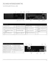
DELL™ OPTIPLEX™ 390 TECHNICAL GUIDEBOOK -FINAL DESKTOP COMPUTER (DT) VIEW
1
2
3
9 10
11
4 56 7 8
12
13
14 15
FRONT VIEW 1 Optical Drive
BACK VIEW 5 Microphone Connector 9 Padlock Ring
13 Expansion Card Slots(4)
2 Optical Drive Eject Button 6 Headphone Connector 10 Security Cable Slot
3 Power Button, Power Light
4 USB Connectors (2)
7 Drive Activity Light 8 Diagnostic ...
Technical Guide - Page 6
DELL™ OPTIPLEX™ 390 TECHNICAL GUIDEBOOK -FINAL
DT System Board Components
Number
Name
1
Front IO connector (FRONTPANEL))
...16x Connector (SLOT1) System fan Connector (FAN_SYS2) P2 Power Connector(ATX12V) CPU Socket Connector (U27CPU) CPU fan Connector (FAN_CPU) Memory Connector(DIMM1) P1 power Connector (ATX) Power Switch Connector (PWRSW1) Memory Connector(DIMM2) Battery Connector...
Technical Guide - Page 7
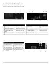
DELL™ OPTIPLEX™ 390 TECHNICAL GUIDEBOOK -FINAL SMALL FORM FACTOR COMPUTER (SFF) VIEW
1
2
3
9
10
11 12 13
4 56
7 8
14
15
FRONT VIEW
1 Optical Drive
5 Microphone Connector
2 Optical Drive Eject Button 6 Headphone Connector
3 Power Button, Power Light
4 USB 2.0 Connectors (2)
7 Diagnostic Lights (4) 8 Drive Activity Light
BACK VIEW 9 Padlock Ring
10 Security Cable Slot 11...
Technical Guide - Page 18
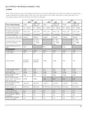
DELL™ OPTIPLEX™ 390 TECHNICAL GUIDEBOOK -FINAL POWER
NOTE: These form factors utilize a more than one 12v rail)
BTUs/h (based on Sine Wave output for APFC PSUs, not an approximation of a Sine Wave, Square Wave, or quasi-Square Wave. Power Supply Wattage AC input Voltage Range
265W
MT
APFC
EPA
265W High
Efficiency
90 - 264Vac 90...
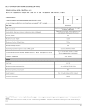
Technical Guide - Page 19
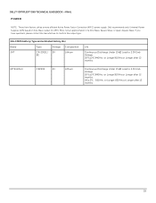
DELL™ OPTIPLEX™ 390 TECHNICAL GUIDEBOOK -FINAL POWER
NOTE: These form factors utilize a more efficient Active Power Factor Correction (APFC) power supply. MITSUBISHI
CR2302
3V
Lithium.... 0℃±2℃. 850Hrs. or Longer.910Hrs.or Longer after 12 months.
Dell recommends only Universal Power Supplies (UPS) based on Sine Wave output for APFC PSUs, not an approximation of ...
Technical Guide - Page 20
...; OPTIPLEX™ 390 TECHNICAL GUIDEBOOK -FINAL
AUDIO
INTEGRATED CONEXANT CX20641 HIGH DEFINITION AUDIO High Definition Stereo support Number of channels Number of Bits / Audio resolution
Sampling rate (recording/playback)
Signal to Noise Ratio Analog Audio Dolby Digital THX Digital out (S/PDIF) Audio Jack Impedance
Microphone Line-In Line-Out Headphone Internal Speaker Power...
Technical Guide - Page 25
...: Analog and/or digital)
External Connectors HDMI Bus Type Maximum supported resolution Maximum power consumption Audio Support External connectors
MT
DT
SFF
Integrated Gen6 Core Intel® HD... VGA can be used concurrently for multi-monitor display in DOS
25 The DisplayPort controller does not support multi-monitor display in DOS. DELL™ OPTIPLEX™ 390 TECHNICAL GUIDEBOOK -FINAL...
Technical Guide - Page 31

... size Access Times (typical) Maximum Data Transfer Rates Writes Reads Power Source DC Power Requirements
SATA 1.5Gbit/s Standard
supplier dependent supplier dependent
16x DVD...; using DVD+R media provides maximum compatibility. RW1
External Dimensions inches/ centimeters (Without Bezel - DVD-ROM
External Dimensions inches/ centimeters (Without Bezel - DELL™ OPTIPLEX™ 390 TECHNICAL...
Technical Guide - Page 33
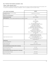
...
Memory Stick (MS) Specification 1.43 xD Specification 1.2
Power Source
Max Power Requirements
2.5W
Supply Voltage Range
4.75V ~ 5.25V
Power Consumption: Environmental Operating Conditions (Non-Condensing):
Standby less than... a F5 to 95% RH
33 DELL™ OPTIPLEX™ 390 TECHNICAL GUIDEBOOK -FINAL
MEDIA CARD READER (MCR) NOTE: Dell 19 in 1 Media Card Reader (MCR) is ...
Technical Guide - Page 36
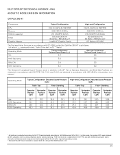
... Declared Noise Emission in accordance with ISO 9296 for the Dell OptiPlex 390 MT is as follows: (all values LWAd expressed in bels; 1 bel=10 decibels, re 10-12 Watts)
Operating Mode Idle
Typical Configuration Declared Sound Power (LWAd)
3.4
High-end Configuration Declared Sound Power (LWAd)
3.5
HDD Operating
3.6
3.5
90% CPU ODD Operating
3.6
3.5
5.2
5.2
The Declared A-weighted...
Technical Guide - Page 37
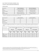
...-12 Watts)
Operating Mode Idle
Typical Configuration Declared Sound Power (LWAd)
3.4
High-end Configuration Declared Sound Power (LWAd)
3.4
HDD Operating
3.4
3.4
90% CPU ODD Operating
4.0
4.1
5.2
5.2
The Declared A-weighted Sound Pressure Level in decibels (re 2x10⁻⁵ Pa), at 90% utilization with ISO 9296 for the Dell OptiPlex 390 DT is as follows1:
Operating Mode
Idle HDD Operating...
Technical Guide - Page 38

... in accordance with no other reported operating modes. 2 Declared Sound Power rounded to ISO 9296 except 90% CPU. For this product is not specified in ISO 7779, but was measured using the same microphone distances and measurement techniques defined for the Dell OptiPlex 390 SFF is as
Operating Mode
Typical Configuration Declared Sound Pressure (LpA...
Owners Manual - Page 68

... connections from the system board, then press and hold the power supply test button at the rear of the power supply unit.
Press and hold the power supply button. Plug the computer into a working electrical outlet and press the power button. If it illuminates, there could be a problem with the power supply.
68 Problem Description A possible system board failure has occurred. LED...
Owners Manual - Page 85
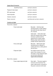
... 24-pin and one 4-pin connector
Controls and Lights Front of the computer:
Power button light
Drive activity light Diagnostic lights
Back of the computer. blinking blue light indicates sleep state of the computer: Power supply diagnostic light
Blue light - Blue light - The power cable must be connected to the hard drive. Four lights located on state...
Similar Questions

Dell Optiplex 790 Power Supply Failure
When pushing the power button on the unit nothing happens. Is this probably the power supply.
When pushing the power button on the unit nothing happens. Is this probably the power supply.
(Posted by frankcurtiss 10 years ago)

What Is Button On Back Of Optiplex 390 Power Supply
(Posted by jac11ddudle 10 years ago)


