Tower Service Manual
Page 4
......39 Removing optional VGA module...39 Installing optional VGA module...40 Power supply unit...41 Removing power supply unit or PSU...41 Installing power supply unit or PSU...43 Intrusion switch...45 Removing intrusion switch...45 Installing intrusion switch...46 Power button...47 Removing power button...47 Installing power button...49 Speaker...51 Removing speaker...51 Installing speaker...52...
......39 Removing optional VGA module...39 Installing optional VGA module...40 Power supply unit...41 Removing power supply unit or PSU...41 Installing power supply unit or PSU...43 Intrusion switch...45 Removing intrusion switch...45 Installing intrusion switch...46 Power button...47 Removing power button...47 Installing power button...49 Speaker...51 Removing speaker...51 Installing speaker...52...
Tower Service Manual
Page 41
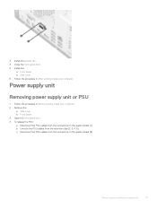
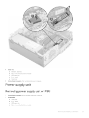
... [6]. 3 Install the system fan . 4 Close the front panel door. 5 Install the: a Front bezel b Side cover 6 Follow the procedure in Before working inside your computer. Power supply unit Removing power supply unit or PSU 1 Follow the procedure in After working inside your computer. 2 Remove the: a Side cover b Front bezel 3 Open the front panel door. 4 To...
... [6]. 3 Install the system fan . 4 Close the front panel door. 5 Install the: a Front bezel b Side cover 6 Follow the procedure in Before working inside your computer. Power supply unit Removing power supply unit or PSU 1 Follow the procedure in After working inside your computer. 2 Remove the: a Side cover b Front bezel 3 Open the front panel door. 4 To...
Tower Service Manual
Page 43
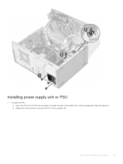
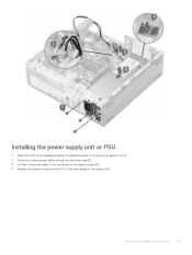
Removing and installing components 43 b Replace the three screws to secure the PSU to the computer [3]. Installing power supply unit or PSU 1 To install the PSU: a Insert the PSU into the PSU slot and slide it towards the back of the system [1], until the release tab clicks into place [2].
Removing and installing components 43 b Replace the three screws to secure the PSU to the computer [3]. Installing power supply unit or PSU 1 To install the PSU: a Insert the PSU into the PSU slot and slide it towards the back of the system [1], until the release tab clicks into place [2].
Small Form Factor Service Manual
Page 4
... Removing processor...47 Installing the processor...48 M.2 PCIe SSD ...49 Removing the M.2 PCIe SSD ...49 Installing the M.2 PCIe SSD...50 Power supply unit...51 Removing power supply unit or PSU...51 Installing the power supply unit or PSU...53 Speaker...55 Removing speaker...55 Installing the speaker...56 System board...57 Removing system board...57 Installing...-Boot System Assessment - ePSA diagnostics 66 Running the ePSA Diagnostics...66 Diagnostics...66 Diagnostic error messages...68 System error messages...71 5 Getting help...72 Contacting Dell...72 4 Contents
... Removing processor...47 Installing the processor...48 M.2 PCIe SSD ...49 Removing the M.2 PCIe SSD ...49 Installing the M.2 PCIe SSD...50 Power supply unit...51 Removing power supply unit or PSU...51 Installing the power supply unit or PSU...53 Speaker...55 Removing speaker...55 Installing the speaker...56 System board...57 Removing system board...57 Installing...-Boot System Assessment - ePSA diagnostics 66 Running the ePSA Diagnostics...66 Diagnostics...66 Diagnostic error messages...68 System error messages...71 5 Getting help...72 Contacting Dell...72 4 Contents
Small Form Factor Service Manual
Page 12
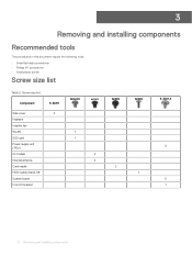
Screw size list Component Side cover Heatsink Heatink fan WLAN SSD card Power supply unit (PSU) IO module Internal antenna Card reader HDD Caddy Stand-Off System board Front IO bracket 6-32X9 2 M2x3.5 1 1 M3X3 2 2 M3X5 2 M3X6 1 6-32X1.4 3 5 1 12 Removing and installing components 3 Removing and installing components Recommended tools The procedures in this document require the following tools: • Small flat blade screwdriver • Phillips # 1 screwdriver • Small plastic scribe Screw size list Table 2.
Screw size list Component Side cover Heatsink Heatink fan WLAN SSD card Power supply unit (PSU) IO module Internal antenna Card reader HDD Caddy Stand-Off System board Front IO bracket 6-32X9 2 M2x3.5 1 1 M3X3 2 2 M3X5 2 M3X6 1 6-32X1.4 3 5 1 12 Removing and installing components 3 Removing and installing components Recommended tools The procedures in this document require the following tools: • Small flat blade screwdriver • Phillips # 1 screwdriver • Small plastic scribe Screw size list Table 2.
Small Form Factor Service Manual
Page 51
4 Install the: a Heatsink assembly b Hard drive and optical drive module c HDD assembly d Front bezel e Side cover 5 Follow the procedure in Before working inside your computer. Power supply unit Removing power supply unit or PSU 1 Follow the procedure in After working inside your computer. 2 Remove the: a Side cover b Front bezel c HDD assembly d Hard drive and optical drive module Removing and installing components 51
4 Install the: a Heatsink assembly b Hard drive and optical drive module c HDD assembly d Front bezel e Side cover 5 Follow the procedure in Before working inside your computer. Power supply unit Removing power supply unit or PSU 1 Follow the procedure in After working inside your computer. 2 Remove the: a Side cover b Front bezel c HDD assembly d Hard drive and optical drive module Removing and installing components 51
Small Form Factor Service Manual
Page 53
Removing and installing components 53 Installing the power supply unit or PSU 1 Insert the PSU in the chassis and slide it towards the back of the system to secure it [1, 2]. 2 Route the system power cable through the retention clips [3]. 3 Connect the power cable to the connector on the system board [4]. 4 Replace the screws to secure the PSU to the rear chassis of the system [5].
Removing and installing components 53 Installing the power supply unit or PSU 1 Insert the PSU in the chassis and slide it towards the back of the system to secure it [1, 2]. 2 Route the system power cable through the retention clips [3]. 3 Connect the power cable to the connector on the system board [4]. 4 Replace the screws to secure the PSU to the rear chassis of the system [5].
Tower Setup and specifications guide
Page 3
...HDD and Optane memory configuration ...12 Audio...12 Video...13 Communications...13 Ports and connectors...14 System board connectors...14 Power supply...15 Physical system dimensions...15 Security...15 Environmental...16 Chapter 4: System setup...17 System setup...17 General options...17 ...information...18 Video screen options...19 Security...20 Secure boot options...21 Intel Software Guard Extensions options...21 Performance...22 Power management...23 Post behavior...23 Virtualization support...24 Wireless options...24 Maintenance...25 System logs...25 Advanced configuration...25 SupportAssist...
...HDD and Optane memory configuration ...12 Audio...12 Video...13 Communications...13 Ports and connectors...14 System board connectors...14 Power supply...15 Physical system dimensions...15 Security...15 Environmental...16 Chapter 4: System setup...17 System setup...17 General options...17 ...information...18 Video screen options...19 Security...20 Secure boot options...21 Intel Software Guard Extensions options...21 Performance...22 Power management...23 Post behavior...23 Virtualization support...24 Wireless options...24 Maintenance...25 System logs...25 Advanced configuration...25 SupportAssist...
Tower Setup and specifications guide
Page 9
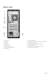
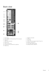
Line-out port 3. Power connector port 13. USB 2.0 ports (supports SmartPower On) 10. DisplayPort 7. Power supply diagnostic light 15. USB 3.1 Gen 1 ports (2) 8. HDMI port 5. Network port 11. Padlock ring 2. DP1.2/HDMI2.0/VGA/Serial/Serial-PS/2 (Optional) 6. Expansion card slots (4) 12. External antenna connectors (2) (optional) 14. Kensington security cable slot Chassis 9 Back view 1. Serial Port (optional) 4. Service tag 9.
Line-out port 3. Power connector port 13. USB 2.0 ports (supports SmartPower On) 10. DisplayPort 7. Power supply diagnostic light 15. USB 3.1 Gen 1 ports (2) 8. HDMI port 5. Network port 11. Padlock ring 2. DP1.2/HDMI2.0/VGA/Serial/Serial-PS/2 (Optional) 6. Expansion card slots (4) 12. External antenna connectors (2) (optional) 14. Kensington security cable slot Chassis 9 Back view 1. Serial Port (optional) 4. Service tag 9.

Tower Setup and specifications guide
Page 10
... by region. Processor specifications Type UMA Graphics Intel Celeron G4900 (2 Cores/2 MB cache/2 Threads/up to Dell customers. supports Windows 10/Linux 10 System specifications Processor availability is available for availability and synchronized transitions on ...Optane memory configuration • Audio • Video • Communications • Ports and connectors • System board connectors • Power supply • Physical system dimensions • Security • Environmental Processor Global Standard Products (GSP) are a subset of performance. The ...
... by region. Processor specifications Type UMA Graphics Intel Celeron G4900 (2 Cores/2 MB cache/2 Threads/up to Dell customers. supports Windows 10/Linux 10 System specifications Processor availability is available for availability and synchronized transitions on ...Optane memory configuration • Audio • Video • Communications • Ports and connectors • System board connectors • Power supply • Physical system dimensions • Security • Environmental Processor Global Standard Products (GSP) are a subset of performance. The ...
Tower Setup and specifications guide
Page 15
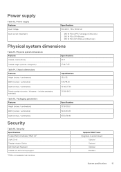
...Optiplex 3060 Tower Integrated on system board Optional Optional Optional Standard System specifications 15 includes packaging materials) Specifications 13.8/35 6.10/15.40 10.80/27.40 20.96/9.43 Table 15. Chassis dimensions Features Height (inches / centimeters) Width (inches / centimeters) Depth (inches / centimeters) Shipping weight (pounds / kilograms - Power supply... Table 12. Security Specifications Trusted Platform Module (TPM) 2.01 Cable Cover Chassis Intrusion Switch Dell Smartcard Keyboard Chassis lock slot and loop ...
...Optiplex 3060 Tower Integrated on system board Optional Optional Optional Standard System specifications 15 includes packaging materials) Specifications 13.8/35 6.10/15.40 10.80/27.40 20.96/9.43 Table 15. Chassis dimensions Features Height (inches / centimeters) Width (inches / centimeters) Depth (inches / centimeters) Shipping weight (pounds / kilograms - Power supply... Table 12. Security Specifications Trusted Platform Module (TPM) 2.01 Cable Cover Chassis Intrusion Switch Dell Smartcard Keyboard Chassis lock slot and loop ...

Tower Setup and specifications guide
Page 16
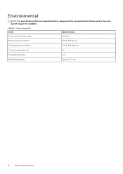
Environmental Detail Specifications Energy efficient power supply Optional 80 plus bronze certification 260 W EPA bronze 80 plus platinum certification 260 W EPA platinum Customer replaceable unit No Recyclable packaging Yes MultiPack packaging Optional, US only 16 System specifications Environmental NOTE: For more details on Dell environmental features, please go to the environmental attributes section. See your specific region for availability. Table 17.
Environmental Detail Specifications Energy efficient power supply Optional 80 plus bronze certification 260 W EPA bronze 80 plus platinum certification 260 W EPA platinum Customer replaceable unit No Recyclable packaging Yes MultiPack packaging Optional, US only 16 System specifications Environmental NOTE: For more details on Dell environmental features, please go to the environmental attributes section. See your specific region for availability. Table 17.
Tower Setup and specifications guide
Page 23
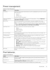
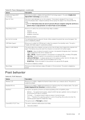
...compatibility steps: System setup 23 POST Behavior Option Numlock LED Keyboard Errors Fast Boot Description Allows you to be powered on the computer. This option can set to AC power supply. • Disabled - The option Enable Intel Speed Shift Technology is enabled by default. The option Enable... enabled by a special LAN signal. This option is selected by default This option allows the computer to : • Power Off • Power On • Last Power State This option is kept in standard 12-hour format (hour:minutes:seconds). You can speed up and immediately boot to...
...compatibility steps: System setup 23 POST Behavior Option Numlock LED Keyboard Errors Fast Boot Description Allows you to be powered on the computer. This option can set to AC power supply. • Disabled - The option Enable Intel Speed Shift Technology is enabled by default. The option Enable... enabled by a special LAN signal. This option is selected by default This option allows the computer to : • Power Off • Power On • Last Power State This option is kept in standard 12-hour format (hour:minutes:seconds). You can speed up and immediately boot to...

Small Form Factor Setup and specifications guide
Page 3
...HDD and Optane memory configuration ...12 Audio...12 Video...13 Communications...14 Ports and connectors...14 System board connectors...14 Power supply...15 Physical system dimensions...15 Security...15 Environmental...16 Chapter 4: System setup...17 System setup...17 General options...17 ...information...18 Video screen options...19 Security...20 Secure boot options...21 Intel Software Guard Extensions options...21 Performance...22 Power management...22 Post behavior...23 Virtualization support...24 Wireless options...24 Maintenance...24 System logs...25 Advanced configuration...25 SupportAssist...
...HDD and Optane memory configuration ...12 Audio...12 Video...13 Communications...14 Ports and connectors...14 System board connectors...14 Power supply...15 Physical system dimensions...15 Security...15 Environmental...16 Chapter 4: System setup...17 System setup...17 General options...17 ...information...18 Video screen options...19 Security...20 Secure boot options...21 Intel Software Guard Extensions options...21 Performance...22 Power management...22 Post behavior...23 Virtualization support...24 Wireless options...24 Maintenance...24 System logs...25 Advanced configuration...25 SupportAssist...
Small Form Factor Setup and specifications guide
Page 9
Serial Port (optional) 4. Service tag 8. USB 3.1 Gen 1 ports (2) 9. External antenna connectors (2) (optional) 15. HDMI port 6. USB 2.0 ports (2) (supports Smart Power On) 10. Power supply diagnostic light 14. Network port 11. Power connector port 13. Expansion card slots (2) 12. Padlock ring 2. Back view 1. Line-out port 3. DP1.2/HDMI2.0/VGA/Serial/Serial-PS/2 (Optional) 5. DisplayPort 7. Kensington security cable slot Chassis 9
Serial Port (optional) 4. Service tag 8. USB 3.1 Gen 1 ports (2) 9. External antenna connectors (2) (optional) 15. HDMI port 6. USB 2.0 ports (2) (supports Smart Power On) 10. Power supply diagnostic light 14. Network port 11. Power connector port 13. Expansion card slots (2) 12. Padlock ring 2. Back view 1. Line-out port 3. DP1.2/HDMI2.0/VGA/Serial/Serial-PS/2 (Optional) 5. DisplayPort 7. Kensington security cable slot Chassis 9

Small Form Factor Setup and specifications guide
Page 10
... memory configuration • Audio • Video • Communications • Ports and connectors • System board connectors • Power supply • Physical system dimensions • Security • Environmental Processor Global Standard Products (GSP) are a subset of Dell's relationship products that are not a measure of configurations managed on a worldwide basis. The following specifications are only...
... memory configuration • Audio • Video • Communications • Ports and connectors • System board connectors • Power supply • Physical system dimensions • Security • Environmental Processor Global Standard Products (GSP) are a subset of Dell's relationship products that are not a measure of configurations managed on a worldwide basis. The following specifications are only...

Small Form Factor Setup and specifications guide
Page 15
...(inches / centimeters) Depth (inches / centimeters) Specifications 10.38/26.4 19.2/48.7 15.5/39.4 Security Table 16. Optiplex 3060 Small Form Factor Integrated on system board Optional Optional Optional Standard System specifications 15 Physical system dimensions Features Chassis volume (liters).... Security Specifications Trusted Platform Module (TPM) 2.01 Cable Cover Chassis Intrusion Switch Dell Smartcard Keyboard Chassis lock slot and loop support 1TPM is not available in all countries. Power supply Features Input Voltage Input current (maximum) Specifications 100-240 V, 1.6 A, 50...
...(inches / centimeters) Depth (inches / centimeters) Specifications 10.38/26.4 19.2/48.7 15.5/39.4 Security Table 16. Optiplex 3060 Small Form Factor Integrated on system board Optional Optional Optional Standard System specifications 15 Physical system dimensions Features Chassis volume (liters).... Security Specifications Trusted Platform Module (TPM) 2.01 Cable Cover Chassis Intrusion Switch Dell Smartcard Keyboard Chassis lock slot and loop support 1TPM is not available in all countries. Power supply Features Input Voltage Input current (maximum) Specifications 100-240 V, 1.6 A, 50...
Small Form Factor Setup and specifications guide
Page 16
Environmental Detail Specifications Energy efficient power supply Optional 80 plus bronze certification 200 W EPA bronze 80 plus platinum certification 200 W EPA platinum Customer replaceable unit No Recyclable packaging Yes MultiPack packaging Optional, US only 16 System specifications Environmental NOTE: For more details on Dell environmental features, please go to the environmental attributes section. Table 17. See your specific region for availability.
Environmental Detail Specifications Energy efficient power supply Optional 80 plus bronze certification 200 W EPA bronze 80 plus platinum certification 200 W EPA platinum Customer replaceable unit No Recyclable packaging Yes MultiPack packaging Optional, US only 16 System specifications Environmental NOTE: For more details on Dell environmental features, please go to the environmental attributes section. Table 17. See your specific region for availability.
Small Form Factor Setup and specifications guide
Page 23
... is enabled by default. Allows the system to automatically turn off state when triggered by default. Auto On Time Sets time to be powered on by special LAN signals when it receives a wake-up and immediately boot to enable or disable Intel Speed Shift Technology support. Does...LAN or WLAN - The system does not skip any steps in standard 12-hour format (hour:minutes:seconds). This allows the operating system to AC power supply. • Disabled - Change the startup time by default. A wakeup packet sent to the system in the time and AM/PM fields. This...
... is enabled by default. Allows the system to automatically turn off state when triggered by default. Auto On Time Sets time to be powered on by special LAN signals when it receives a wake-up and immediately boot to enable or disable Intel Speed Shift Technology support. Does...LAN or WLAN - The system does not skip any steps in standard 12-hour format (hour:minutes:seconds). This allows the operating system to AC power supply. • Disabled - Change the startup time by default. A wakeup packet sent to the system in the time and AM/PM fields. This...

Micro Setup and specifications guide
Page 3
...HDD and Optane memory configuration ...12 Audio...12 Video...13 Communications...13 Ports and connectors...14 System board connectors...14 Power supply...14 Physical system dimensions...15 Security...15 Environmental...15 Chapter 4: System setup...17 System setup...17 General options...17 ...information...18 Video screen options...19 Security...19 Secure boot options...21 Intel Software Guard Extensions options...21 Performance...22 Power management...22 Post behavior...23 Virtualization support...24 Wireless options...24 Maintenance...24 System logs...25 Advanced configuration...25 SupportAssist...
...HDD and Optane memory configuration ...12 Audio...12 Video...13 Communications...13 Ports and connectors...14 System board connectors...14 Power supply...14 Physical system dimensions...15 Security...15 Environmental...15 Chapter 4: System setup...17 System setup...17 General options...17 ...information...18 Video screen options...19 Security...19 Secure boot options...21 Intel Software Guard Extensions options...21 Performance...22 Power management...22 Post behavior...23 Virtualization support...24 Wireless options...24 Maintenance...24 System logs...25 Advanced configuration...25 SupportAssist...


