Service Manual
Page 3
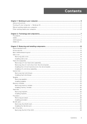
... your computer...6 Chapter 2: Technology and components 7 Processors...7 DDR4...7 USB features...8 HDMI 2.0...10 Chapter 3: Removing and installing components 12 Recommended tools...12 Screw size list...12 Micro Motherboard Layout...13 Side cover...14 Removing side cover...14 Installing side cover...15 Hard drive assembly...17 Removing 2.5-inch hard drive assembly...17 Removing the...
... your computer...6 Chapter 2: Technology and components 7 Processors...7 DDR4...7 USB features...8 HDMI 2.0...10 Chapter 3: Removing and installing components 12 Recommended tools...12 Screw size list...12 Micro Motherboard Layout...13 Side cover...14 Removing side cover...14 Installing side cover...15 Hard drive assembly...17 Removing 2.5-inch hard drive assembly...17 Removing the...

Service Manual
Page 12
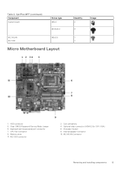
... from your computer depending on the configuration you ordered. OptiPlex MFF Component Base cover Screw type #6.32x9.3 Quantity 1 Image Speaker Type-C module bracket AUX antenna M2.5X4 2 M3X3 1 2 12 Removing and installing components Topics: • Recommended tools • Screw size list • Micro Motherboard Layout • Side cover • Hard drive assembly •...
... from your computer depending on the configuration you ordered. OptiPlex MFF Component Base cover Screw type #6.32x9.3 Quantity 1 Image Speaker Type-C module bracket AUX antenna M2.5X4 2 M3X3 1 2 12 Removing and installing components Topics: • Recommended tools • Screw size list • Micro Motherboard Layout • Side cover • Hard drive assembly •...
Service Manual
Page 13
HDD connector 3. Optional video connector (HDMI 2.0b / DP/ VGA) 6. Keyboard and mouse serial port connector 7. M.2 SSD connector 2. CPU Fan Connector 9. Coin cell battery 4. Processor Socket 8. Clear CMOS/Password/Service Mode Jumper 5. M.2 WLAN Connector Removing and installing components 13 Memory slots 11. OptiPlex MFF (continued) Component System board Screw type M3x4 #6.32x5.4 M.2 WLAN M.2 SSD M2x3.5 Micro Motherboard Layout Quantity 2 3 1 1 Image 1. Internal speaker Connector 10. Table 2.
HDD connector 3. Optional video connector (HDMI 2.0b / DP/ VGA) 6. Keyboard and mouse serial port connector 7. M.2 SSD connector 2. CPU Fan Connector 9. Coin cell battery 4. Processor Socket 8. Clear CMOS/Password/Service Mode Jumper 5. M.2 WLAN Connector Removing and installing components 13 Memory slots 11. OptiPlex MFF (continued) Component System board Screw type M3x4 #6.32x5.4 M.2 WLAN M.2 SSD M2x3.5 Micro Motherboard Layout Quantity 2 3 1 1 Image 1. Internal speaker Connector 10. Table 2.
Service Manual
Page 48
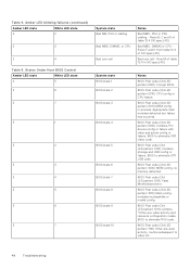
... 0001) Corrupt BIOS. BIOS Post code (Old LED pattern 0110) Combine storage and USB config or failure. BIOS Post code (Old LED pattern 1001) Fatal Motherboard error. BIOS Post code (Old LED pattern 1011) combine "Other pre-video activity and resource configuration codes. BIOS to video init. 48 Troubleshooting Amber LED...
... 0001) Corrupt BIOS. BIOS Post code (Old LED pattern 0110) Combine storage and USB config or failure. BIOS Post code (Old LED pattern 1001) Fatal Motherboard error. BIOS Post code (Old LED pattern 1011) combine "Other pre-video activity and resource configuration codes. BIOS to video init. 48 Troubleshooting Amber LED...

Service Manual
Page 52
... a boot device. ● Enter system setup and ensure that a parameter has exceeded its factory state. No bootable partition on your Dell PC. Recovering the operating system When your computer boots to the operating system. It enables you back up your files, or restore your... www.dell.com/serviceabilitytools. Dell recommends that is a standalone tool that you to software or hardware failures. System fan has failed. Possible hard disk drive failure during POST. The legacy jumper enabled RTC reset has been retired on the system board might be malfunctioning or motherboard failure...
... a boot device. ● Enter system setup and ensure that a parameter has exceeded its factory state. No bootable partition on your Dell PC. Recovering the operating system When your computer boots to the operating system. It enables you back up your files, or restore your... www.dell.com/serviceabilitytools. Dell recommends that is a standalone tool that you to software or hardware failures. System fan has failed. Possible hard disk drive failure during POST. The legacy jumper enabled RTC reset has been retired on the system board might be malfunctioning or motherboard failure...


