User Manual
Page 1
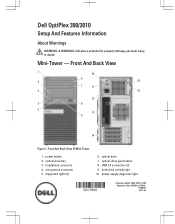
diagnostic lights (4) 6. USB 2.0 connectors (2) 9. Front And Back View Of Mini-Tower 1. optical-drive eject button 8. hard-drive activity light 10. Mini-Tower - power button 2. optical drive bay 3. microphone connector 5. optical drive 7. Front And Back View Figure 1. Dell OptiPlex 390/3010 Setup And Features Information About Warnings WARNING: A WARNING indicates a potential for property damage, personal injury, or death. headphone connector 4. power-supply diagnostic light Regulatory Model: D04S, D07D, D12M Regulatory Type: D04S001, D07D001, D12M001 2012 - 05
diagnostic lights (4) 6. USB 2.0 connectors (2) 9. Front And Back View Of Mini-Tower 1. optical-drive eject button 8. hard-drive activity light 10. Mini-Tower - power button 2. optical drive bay 3. microphone connector 5. optical drive 7. Front And Back View Figure 1. Dell OptiPlex 390/3010 Setup And Features Information About Warnings WARNING: A WARNING indicates a potential for property damage, personal injury, or death. headphone connector 4. power-supply diagnostic light Regulatory Model: D04S, D07D, D12M Regulatory Type: D04S001, D07D001, D12M001 2012 - 05
User Manual
Page 2
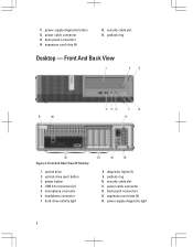
back panel connectors 14. Front And Back View Figure 2. optical-drive eject button 3. power button 4. expansion card slots (4) 15. USB 2.0 connectors (2) 5. power cable connector 12. expansion card slots (4) 14. microphone connector 6. power-supply diagnostic light 2 power-supply diagnostic button 12. Front And Back View Of Desktop 1. security cable slot 11. padlock ring 10. back panel connectors 13. power cable connector 13. security cable slot 16. optical drive 2. hard-drive activity light 8. padlock ring Desktop - headphone connector 7. ...
back panel connectors 14. Front And Back View Figure 2. optical-drive eject button 3. power button 4. expansion card slots (4) 15. USB 2.0 connectors (2) 5. power cable connector 12. expansion card slots (4) 14. microphone connector 6. power-supply diagnostic light 2 power-supply diagnostic button 12. Front And Back View Of Desktop 1. security cable slot 11. padlock ring 10. back panel connectors 13. power cable connector 13. security cable slot 16. optical drive 2. hard-drive activity light 8. padlock ring Desktop - headphone connector 7. ...
User Manual
Page 3
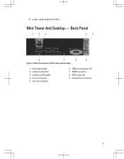
line-in connector 5. USB 2.0 connectors (6) 7. microphone connector 3 15. power-supply diagnostic button Mini-Tower And Desktop - Back Panel View of Mini-Tower And Desktop 1. line-out connector 6. VGA connector 9. network activity light 4. network connector 3. link integrity light 2. HDMI connector 8. Back Panel Figure 3.
line-in connector 5. USB 2.0 connectors (6) 7. microphone connector 3 15. power-supply diagnostic button Mini-Tower And Desktop - Back Panel View of Mini-Tower And Desktop 1. line-out connector 6. VGA connector 9. network activity light 4. network connector 3. link integrity light 2. HDMI connector 8. Back Panel Figure 3.

User Manual
Page 4
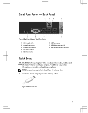
Front And Back View Of Small Form Factor 1. optical-drive eject button 3. headphone connector 7. back panel connectors 15. USB 2.0 connectors (2) 5. hard-drive activity light 9. power cable connector 12. expansion card slots (2) 4 diagnostic lights (4) 8. power-supply diagnostic button 13. power button 4. microphone connector 6. optical drive 2. padlock ring 10. power-supply diagnostic light 14. Small Form Factor - Front And Back View Figure 4. security cable slot 11.
Front And Back View Of Small Form Factor 1. optical-drive eject button 3. headphone connector 7. back panel connectors 15. USB 2.0 connectors (2) 5. hard-drive activity light 9. power cable connector 12. expansion card slots (2) 4 diagnostic lights (4) 8. power-supply diagnostic button 13. power button 4. microphone connector 6. optical drive 2. padlock ring 10. power-supply diagnostic light 14. Small Form Factor - Front And Back View Figure 4. security cable slot 11.
User Manual
Page 5
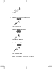
USB 2.0 connectors (6) 8. For additional best practices information, see www.dell.com/regulatory_compliance NOTE: Some devices may not be included if you begin any of the procedures in this section, read the safety information that shipped ...
USB 2.0 connectors (6) 8. For additional best practices information, see www.dell.com/regulatory_compliance NOTE: Some devices may not be included if you begin any of the procedures in this section, read the safety information that shipped ...
User Manual
Page 6
Connect the network cable (optional). Connect the USB keyboard or mouse (optional). Figure 8. VGA Connector 2. Connect the power cable(s). Connecting Power 5. USB Connection 3. Network Connection 4. Press the power buttons on the monitor and the computer. 6 Figure 9. Figure 10. Figure 7.
Connect the network cable (optional). Connect the USB keyboard or mouse (optional). Figure 8. VGA Connector 2. Connect the power cable(s). Connecting Power 5. USB Connection 3. Network Connection 4. Press the power buttons on the monitor and the computer. 6 Figure 9. Figure 10. Figure 7.

User Manual
Page 7
... Form Factor Maximum heat dissipation Desktop Mini-Tower Small Form Factor 3 V CR2032 lithium coin cell 100 VAC to ship with your computer, go to support.dell.com. Figure 11. For a complete and current listing of the specifications for your computer.
... Form Factor Maximum heat dissipation Desktop Mini-Tower Small Form Factor 3 V CR2032 lithium coin cell 100 VAC to ship with your computer, go to support.dell.com. Figure 11. For a complete and current listing of the specifications for your computer.

User Manual
Page 8
... the safety and regulatory documents that shipped with your computer and the regulatory compliance website at www.dell.com/regulatory_compliance for more information on: • Safety best practices • Regulatory certification • Ergonomics See www.dell.com for additional information on the device described in this document in compliance with the requirements...
... the safety and regulatory documents that shipped with your computer and the regulatory compliance website at www.dell.com/regulatory_compliance for more information on: • Safety best practices • Regulatory certification • Ergonomics See www.dell.com for additional information on the device described in this document in compliance with the requirements...
User Manual
Page 9
...™, Precision ON™, ExpressCharge™, Latitude™, Latitude ON™, OptiPlex™, Vostro™, and Wi-Fi Catcher™ are either the entities claiming the marks and names or their products, Dell Inc. AMD® is a trademark owned by the Blu-ray Disc Association (BDA) ...AMD Sempron™, AMD Athlon™, ATI Radeon™, and ATI FirePro™ are registered trademarks or trademarks of Dell Inc. is under license. The Bluetooth® word mark is available at support.dell.com/manuals. and any use on your product is a registered trademark and owned by...
...™, Precision ON™, ExpressCharge™, Latitude™, Latitude ON™, OptiPlex™, Vostro™, and Wi-Fi Catcher™ are either the entities claiming the marks and names or their products, Dell Inc. AMD® is a trademark owned by the Blu-ray Disc Association (BDA) ...AMD Sempron™, AMD Athlon™, ATI Radeon™, and ATI FirePro™ are registered trademarks or trademarks of Dell Inc. is under license. The Bluetooth® word mark is available at support.dell.com/manuals. and any use on your product is a registered trademark and owned by...

Statement of Volatility
Page 1
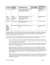
... EEPROM On memory DIMM(s) - Stores memory manufacturer data and timing information for basic boot operation, PSA (on the Dell OptiPlex 3010 motherboard: Description Reference Designator Embedded U36 Flash memory in embedded controller SMSC5514E System U30 BIOS Ethernet U14 Controller Embedded Efuse ...modules and will be between 2GB to retain their data immediately upon removal of Volatility - Dell OptiPlex 3010 To whom it may concern: The Dell OptiPlex 3010 contains both "volatile" and "non-volatile" (NV) components. System memory size will depend on each DIMM...
... EEPROM On memory DIMM(s) - Stores memory manufacturer data and timing information for basic boot operation, PSA (on the Dell OptiPlex 3010 motherboard: Description Reference Designator Embedded U36 Flash memory in embedded controller SMSC5514E System U30 BIOS Ethernet U14 Controller Embedded Efuse ...modules and will be between 2GB to retain their data immediately upon removal of Volatility - Dell OptiPlex 3010 To whom it may concern: The Dell OptiPlex 3010 contains both "volatile" and "non-volatile" (NV) components. System memory size will depend on each DIMM...
Statement of Volatility
Page 2
... data on the system board, i.e. The restore file has to be able to go to S4 if the OS and the peripherals support S4 state. Dell systems will be able to go to S3 if the OS and the peripherals used in different ACPI power states the following is provided (those... Volatile optical/magnetic Yes media Low level format / erase All other components on board Coin Cell battery Video memory - S3 is read/write by mode. Dell systems will be valid. No UMA uses main system memory size allocated out of -day information. Windows 7, support S4 state. The OS does not save...
... data on the system board, i.e. The restore file has to be able to go to S4 if the OS and the peripherals support S4 state. Dell systems will be able to go to S3 if the OS and the peripherals used in different ACPI power states the following is provided (those... Volatile optical/magnetic Yes media Low level format / erase All other components on board Coin Cell battery Video memory - S3 is read/write by mode. Dell systems will be valid. No UMA uses main system memory size allocated out of -day information. Windows 7, support S4 state. The OS does not save...

Statement of Volatility
Page 3
Sincerely, Dell Marketing DELL CONFIDENTIAL Page 3 The following table shows all the states supported by Dell OptiPlex 3010 Model Number S0 S1 S3 S4 S5 Dell OptiPlex X 3010 XX X Please direct any questions to your Dell Marketing contact.
Sincerely, Dell Marketing DELL CONFIDENTIAL Page 3 The following table shows all the states supported by Dell OptiPlex 3010 Model Number S0 S1 S3 S4 S5 Dell OptiPlex X 3010 XX X Please direct any questions to your Dell Marketing contact.
Guidebook
Page 1
INSIDE THE OPTIPLEX 3010 DELL TM OPTIPLEX TM 3010 TECHNICAL GUIDEBOOK-
INSIDE THE OPTIPLEX 3010 DELL TM OPTIPLEX TM 3010 TECHNICAL GUIDEBOOK-
Guidebook
Page 2
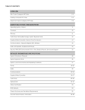
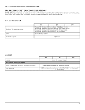
TABLE OF CONTENTS OVERVIEW Mini Tower Computer (MT) View Desktop Computer (DT) View Small Form Factor Computer (SFF) View MARKETING SYSTEM CONFIGURATIONS Operating System, Chipset Processor Memory Hard Drives, Removable Storage, System Expansion Slots Graphics/Video Controller, External Ports/Connectors Communications-Network Adapter (NIC), Wireless Audio and Speakers, Keyboard and Mouse Security HW & SW, Environmental, All-in-One Stands & Mounts, Service and Support DETAILED ENGINEERING SPECIFICATIONS System Dimensions (Physical) System Expansion Slots System Level Environmental and Operating...
TABLE OF CONTENTS OVERVIEW Mini Tower Computer (MT) View Desktop Computer (DT) View Small Form Factor Computer (SFF) View MARKETING SYSTEM CONFIGURATIONS Operating System, Chipset Processor Memory Hard Drives, Removable Storage, System Expansion Slots Graphics/Video Controller, External Ports/Connectors Communications-Network Adapter (NIC), Wireless Audio and Speakers, Keyboard and Mouse Security HW & SW, Environmental, All-in-One Stands & Mounts, Service and Support DETAILED ENGINEERING SPECIFICATIONS System Dimensions (Physical) System Expansion Slots System Level Environmental and Operating...
Guidebook
Page 3
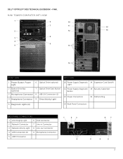
DELL™ OPTIPLEX™ 3010 TECHNICAL GUIDEBOOK -FINAL MINI TOWER COMPUTER (MT) VIEW 1 6 10 7 11 15 2 12 16 8 3 4 9 5 13 14 FRONT VIEW BACK VIEW 1 Power Button, Power Light 6 Optical Drive (...
DELL™ OPTIPLEX™ 3010 TECHNICAL GUIDEBOOK -FINAL MINI TOWER COMPUTER (MT) VIEW 1 6 10 7 11 15 2 12 16 8 3 4 9 5 13 14 FRONT VIEW BACK VIEW 1 Power Button, Power Light 6 Optical Drive (...
Guidebook
Page 4
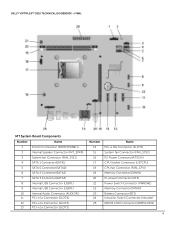
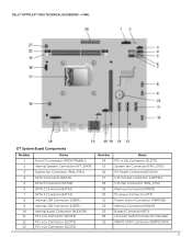
DELL™ OPTIPLEX™ 3010 TECHNICAL GUIDEBOOK -FINAL MT System Board Components Number 1 2 3 4 5 6 7 8 9 10 11 12 13 Name Front IO connector (FRONTPANEL)) Internal Speaker Connector (INT_SPKR) System fan Connector (FAN_SYS1) ...
DELL™ OPTIPLEX™ 3010 TECHNICAL GUIDEBOOK -FINAL MT System Board Components Number 1 2 3 4 5 6 7 8 9 10 11 12 13 Name Front IO connector (FRONTPANEL)) Internal Speaker Connector (INT_SPKR) System fan Connector (FAN_SYS1) ...
Guidebook
Page 5
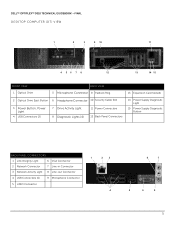
DELL™ OPTIPLEX™ 3010 TECHNICAL GUIDEBOOK -FINAL DESKTOP COMPUTER (DT) VIEW 1 2 3 9 10 11 4 56 7 8 12 13 14 15 FRONT VIEW 1 Optical Drive BACK VIEW 5 Microphone Connector 9 Padlock Ring 13 ...
DELL™ OPTIPLEX™ 3010 TECHNICAL GUIDEBOOK -FINAL DESKTOP COMPUTER (DT) VIEW 1 2 3 9 10 11 4 56 7 8 12 13 14 15 FRONT VIEW 1 Optical Drive BACK VIEW 5 Microphone Connector 9 Padlock Ring 13 ...
Guidebook
Page 6
DELL™ OPTIPLEX™ 3010 TECHNICAL GUIDEBOOK -FINAL DT System Board Components Number Name 1 Front IO connector (FRONTPANEL)) 2 Internal Speaker Connector (INT_SPKR) 3 System fan Connector (FAN_SYS1) 4 SATA 1 Connector(SATA1) 5 SATA 0 ...
DELL™ OPTIPLEX™ 3010 TECHNICAL GUIDEBOOK -FINAL DT System Board Components Number Name 1 Front IO connector (FRONTPANEL)) 2 Internal Speaker Connector (INT_SPKR) 3 System fan Connector (FAN_SYS1) 4 SATA 1 Connector(SATA1) 5 SATA 0 ...
Guidebook
Page 7
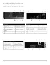
DELL™ OPTIPLEX™ 3010 TECHNICAL GUIDEBOOK -FINAL SMALL FORM FACTOR COMPUTER (SFF) VIEW 1 2 3 9 10 11 12 13 4 56 7 8 14 15 FRONT VIEW 1 Optical Drive 5 Microphone Connector 2 Optical Drive Eject ...
DELL™ OPTIPLEX™ 3010 TECHNICAL GUIDEBOOK -FINAL SMALL FORM FACTOR COMPUTER (SFF) VIEW 1 2 3 9 10 11 12 13 4 56 7 8 14 15 FRONT VIEW 1 Optical Drive 5 Microphone Connector 2 Optical Drive Eject ...
Guidebook
Page 9
... (Serial Peripheral Interface) NIC EEPROM MT DT SFF Intel H61 Express Chipset 64Mbit (8MB) located at SPI_FLASH on chipset LOM configuration contained within SPI_FLASH - DELL™ OPTIPLEX™ 3010 TECHNICAL GUIDEBOOK -FINAL MARKETING SYSTEM CONFIGURATIONS N O T E : O ff e r i n g s m a y v a r y b y c o u n t r y . no dedicated LOM EEPROM 9 F o r m o r e i n f o r m a t i o n r e g a r d i n g t h e c o n fi g u r a t i o n o f y o u r c o m p u t e r , c l i c k Start>Help and Support and select the option to view information about...
... (Serial Peripheral Interface) NIC EEPROM MT DT SFF Intel H61 Express Chipset 64Mbit (8MB) located at SPI_FLASH on chipset LOM configuration contained within SPI_FLASH - DELL™ OPTIPLEX™ 3010 TECHNICAL GUIDEBOOK -FINAL MARKETING SYSTEM CONFIGURATIONS N O T E : O ff e r i n g s m a y v a r y b y c o u n t r y . no dedicated LOM EEPROM 9 F o r m o r e i n f o r m a t i o n r e g a r d i n g t h e c o n fi g u r a t i o n o f y o u r c o m p u t e r , c l i c k Start>Help and Support and select the option to view information about...
