
Service Manual
Page 1
... of your computer. Dell™ OptiPlex™ GX270 Service Manual Safety Instructions Opening the Computer Cover Chassis Intrusion Switch Control Panel I/O Panel Power Supply System Board Closing the Computer Cover To remove or replace all other than its own. Information in this document is strictly forbidden. is subject to hardware or loss of Dell Inc. disclaims any manner whatsoever without notice. © 2003-2004 Dell Inc. Trademarks used in trademarks and...
... of your computer. Dell™ OptiPlex™ GX270 Service Manual Safety Instructions Opening the Computer Cover Chassis Intrusion Switch Control Panel I/O Panel Power Supply System Board Closing the Computer Cover To remove or replace all other than its own. Information in this document is strictly forbidden. is subject to hardware or loss of Dell Inc. disclaims any manner whatsoever without notice. © 2003-2004 Dell Inc. Trademarks used in trademarks and...
Service Manual
Page 2
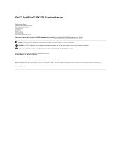
... Intrusion Switch Dell™ OptiPlex™ GX270 Service Manual Removing the Chassis Intrusion Switch Replacing the Chassis Intrusion Switch Resetting the Chassis Intrusion Detector CAUTION: Before you begin any of the chassis intrusion cable as the metal at the back of the computer. NOTICE: To disconnect a network cable, first unplug the cable from your computer and all attached devices from the computer. 4. Open the computer cover. Disconnect...
... Intrusion Switch Dell™ OptiPlex™ GX270 Service Manual Removing the Chassis Intrusion Switch Replacing the Chassis Intrusion Switch Resetting the Chassis Intrusion Detector CAUTION: Before you begin any of the chassis intrusion cable as the metal at the back of the computer. NOTICE: To disconnect a network cable, first unplug the cable from your computer and all attached devices from the computer. 4. Open the computer cover. Disconnect...
Service Manual
Page 3
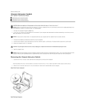
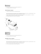
... turn them on the control panel. 2. Connect your computer and devices to the connector on . Small Mini-Tower Computer Replacing the Chassis Intrusion Switch 1. Close the computer cover. 3. or right-arrow key to Enabled, Enabled-Silent, or Disabled. NOTICE: To connect a network cable, first plug the cable into the network wall jack and then plug it is used. Slide the chassis intrusion switch into the computer. 4. NOTE: For instructions on using system setup, see the User's Guide...
... turn them on the control panel. 2. Connect your computer and devices to the connector on . Small Mini-Tower Computer Replacing the Chassis Intrusion Switch 1. Close the computer cover. 3. or right-arrow key to Enabled, Enabled-Silent, or Disabled. NOTICE: To connect a network cable, first plug the cable into the network wall jack and then plug it is used. Slide the chassis intrusion switch into the computer. 4. NOTE: For instructions on using system setup, see the User's Guide...

Service Manual
Page 4
NOTE: The default is Enabled-Silent. Press to Contents Page Back to restart the computer and implement your changes. NOTE: If a setup password has been assigned by someone else, contact the network administrator for information on resetting the chassis intrusion detector. 3.
NOTE: The default is Enabled-Silent. Press to Contents Page Back to restart the computer and implement your changes. NOTE: If a setup password has been assigned by someone else, contact the network administrator for information on resetting the chassis intrusion detector. 3.
Service Manual
Page 5
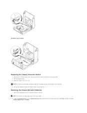
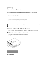
... Contents Page Control Panel Dell™ OptiPlex™ GX270 Service Manual Removing the Control Panel Replacing the Control Panel CAUTION: Before you begin any telephone or telecommunication lines from the electrical outlet before opening the cover. 6. Disconnect your computer and attached devices are turned off . Ensure that your computer and all attached devices from the network wall jack. 3. Removing the Control Panel Small Form-Factor Computer 1. To locate the light, see "System Board." 1. Remove the...
... Contents Page Control Panel Dell™ OptiPlex™ GX270 Service Manual Removing the Control Panel Replacing the Control Panel CAUTION: Before you begin any telephone or telecommunication lines from the electrical outlet before opening the cover. 6. Disconnect your computer and attached devices are turned off . Ensure that your computer and all attached devices from the network wall jack. 3. Removing the Control Panel Small Form-Factor Computer 1. To locate the light, see "System Board." 1. Remove the...

Service Manual
Page 6
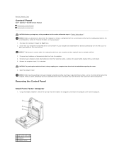
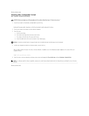
Small Desktop Computer 1. Small Mini-Tower Computer 1. 1 metal control-panel shield 2 screw 2. Remove the front I/O panel (see I/O Panel). 2. Using an 8-inch #2 Phillips screwdriver, remove the screw that holds the control panel to the computer, and lift the panel away from the computer. To remove the top and bottom panels of the computer, remove any installed CD drives and release all the tabs on each panel. Remove the screw that secures the control panel to the computer, and remove the control panel. Remove the metal control-panel shield. 3.
Small Desktop Computer 1. Small Mini-Tower Computer 1. 1 metal control-panel shield 2 screw 2. Remove the front I/O panel (see I/O Panel). 2. Using an 8-inch #2 Phillips screwdriver, remove the screw that holds the control panel to the computer, and lift the panel away from the computer. To remove the top and bottom panels of the computer, remove any installed CD drives and release all the tabs on each panel. Remove the screw that secures the control panel to the computer, and remove the control panel. Remove the metal control-panel shield. 3.

Service Manual
Page 7
Close the computer and remove the computer cover. 5. Replace the control panel and the control-panel shield. NOTE: To release the tab located by the I/O panel). Remove the screw that secures the control panel to access this tab) 4 bottom panel 2 top-panel tabs 5 computer cover screw 3 top panel 6 computer cover tabs (2) 2. 1 computer cover tab (remove the CD drive to the computer, and pull the control panel away from the computer and pull out the...
Close the computer and remove the computer cover. 5. Replace the control panel and the control-panel shield. NOTE: To release the tab located by the I/O panel). Remove the screw that secures the control panel to access this tab) 4 bottom panel 2 top-panel tabs 5 computer cover screw 3 top panel 6 computer cover tabs (2) 2. 1 computer cover tab (remove the CD drive to the computer, and pull the control panel away from the computer and pull out the...
Service Manual
Page 10
...-Factor Computer 1 security cable slot 2 padlock ring 3 release buttons (one on each side) Small Desktop Computer Back to Contents Page Opening the Computer Cover Dell™ OptiPlex™ GX270 Service Manual CAUTION: Before you begin any cables. 2. NOTICE: To disconnect a network cable, first unplug the cable from your computer and then unplug it from the computer. 4. Locate the two release buttons shown in "Safety Instructions." 1. Disconnect any...
...-Factor Computer 1 security cable slot 2 padlock ring 3 release buttons (one on each side) Small Desktop Computer Back to Contents Page Opening the Computer Cover Dell™ OptiPlex™ GX270 Service Manual CAUTION: Before you begin any cables. 2. NOTICE: To disconnect a network cable, first unplug the cable from your computer and then unplug it from the computer. 4. Locate the two release buttons shown in "Safety Instructions." 1. Disconnect any...
Service Manual
Page 12
... way. NOTICE: To connect a network cable, first plug the cable into the network wall jack and then plug it closes. Back to Contents Page Closing the Computer Cover Dell™ OptiPlex™ GX270 Service Manual CAUTION: Before you so that they do not get caught underneath the drives. 2. Back to electrical outlets, and turn them on the screen at the next computer start-up: ALERT! If...
... way. NOTICE: To connect a network cable, first plug the cable into the network wall jack and then plug it closes. Back to Contents Page Closing the Computer Cover Dell™ OptiPlex™ GX270 Service Manual CAUTION: Before you so that they do not get caught underneath the drives. 2. Back to electrical outlets, and turn them on the screen at the next computer start-up: ALERT! If...
Service Manual
Page 13
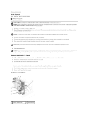
... a network cable, first unplug the cable from your computer and all cables that are turned off . While you work, periodically touch an unpainted metal surface to dissipate any static electricity that you have installed a padlock through the Start menu. 2. Removing the I /O panel. To locate the light, see "System Board." 1. Shut down your computer, turn off now. If you can replace it correctly. 4. Disconnect all attached devices from...
... a network cable, first unplug the cable from your computer and all cables that are turned off . While you work, periodically touch an unpainted metal surface to dissipate any static electricity that you have installed a padlock through the Start menu. 2. Removing the I /O panel. To locate the light, see "System Board." 1. Shut down your computer, turn off now. If you can replace it correctly. 4. Disconnect all attached devices from...
Service Manual
Page 15
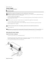
... harm internal components. Open the computer cover. You must route these cables properly when you replace them off when you shut down the computer through the Start menu. 2. Back to Contents Page Power Supply Dell™ OptiPlex™ GX270 Service Manual Removing the Power Supply Replacing the Power Supply CAUTION: Before you begin any telephone or telecommunication lines from the system board and drives. NOTICE: To disconnect a network cable, first unplug the cable from...
... harm internal components. Open the computer cover. You must route these cables properly when you replace them off when you shut down the computer through the Start menu. 2. Back to Contents Page Power Supply Dell™ OptiPlex™ GX270 Service Manual Removing the Power Supply Replacing the Power Supply CAUTION: Before you begin any telephone or telecommunication lines from the system board and drives. NOTICE: To disconnect a network cable, first unplug the cable from...
Service Manual
Page 16
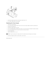
... the clips while you replace them from the system board and drives. Remove the expansion-card cage and remove the power cables from the system board and drives. Note the routing of the computer. Lift the power supply up and out of the DC power cables underneath the tabs in turn presses the release button. 1 release button 2 handle 3 AC power connector 4. Small Desktop Computer 1. Lift the power supply up and out of...
... the clips while you replace them from the system board and drives. Remove the expansion-card cage and remove the power cables from the system board and drives. Note the routing of the computer. Lift the power supply up and out of the DC power cables underneath the tabs in turn presses the release button. 1 release button 2 handle 3 AC power connector 4. Small Desktop Computer 1. Lift the power supply up and out of...
Service Manual
Page 17
.... 3. Lift the power supply up and out of the hard drive and replace the expansion-card cage. 6. Replacing the Power Supply 1. Connect your computer and devices to the side of the computer. Slide the power supply into the computer. 9. NOTICE: To connect a network cable, first plug the cable into the network wall jack and then plug it is used. On the small desktop computer, reattach the power cables to electrical outlets, and turn them over...
.... 3. Lift the power supply up and out of the hard drive and replace the expansion-card cage. 6. Replacing the Power Supply 1. Connect your computer and devices to the side of the computer. Slide the power supply into the computer. 9. NOTICE: To connect a network cable, first plug the cable into the network wall jack and then plug it is used. On the small desktop computer, reattach the power cables to electrical outlets, and turn them over...
Service Manual
Page 18
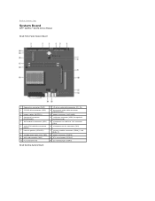
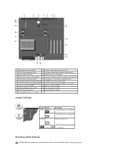
... connector (IDE1) 6 serial ATA hard-drive connector (SATA1) 7 internal speaker (SPEAKER) 8 standby power light (AUX_PWR) 9 AGP card connector (AGP) 10 PCI card connector 11 CD drive audio cable connector (CD_IN) 12 front-panel audio cable connector (FRONTAUDIO) 13 power connector (12VPOWER) 14 serial port connector (SER2) for optional serial port cards 15 microprocessor and heat sink connector (CPU) 16 microprocessor fan connector (FAN) 17 memory module connectors (DIMM_1 and DIMM_2) 18 power connector (POWER) 19 RTC reset jumper (RTCRST) 20 password jumper (PSWD) Small Desktop System Board
... connector (IDE1) 6 serial ATA hard-drive connector (SATA1) 7 internal speaker (SPEAKER) 8 standby power light (AUX_PWR) 9 AGP card connector (AGP) 10 PCI card connector 11 CD drive audio cable connector (CD_IN) 12 front-panel audio cable connector (FRONTAUDIO) 13 power connector (12VPOWER) 14 serial port connector (SER2) for optional serial port cards 15 microprocessor and heat sink connector (CPU) 16 microprocessor fan connector (FAN) 17 memory module connectors (DIMM_1 and DIMM_2) 18 power connector (POWER) 19 RTC reset jumper (RTCRST) 20 password jumper (PSWD) Small Desktop System Board
Service Manual
Page 19
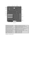
...-panel audio cable connector (FRONTAUDIO) 3 battery socket (BATTERY) 13 power connector (12VPOWER) 4 front-panel connector (FRONTPANEL) 14 serial port connector (SER2) for optional serial port cards 5 IDE hard-drive connector (IDE1) 15 microprocessor and heat sink connector (CPU) 6 serial ATA hard-drive connector (SATA1) 16 microprocessor fan connector (FAN) 7 internal speaker (SPEAKER) 17 memory module connectors (DIMMs 1, 3, 2, and 4) 8 standby power light (AUX_PWR) 18 power connector (POWER) 9 AGP card connector (AGP) 19 RTC reset jumper (RTCRST) 10 PCI riser board connector...
...-panel audio cable connector (FRONTAUDIO) 3 battery socket (BATTERY) 13 power connector (12VPOWER) 4 front-panel connector (FRONTPANEL) 14 serial port connector (SER2) for optional serial port cards 5 IDE hard-drive connector (IDE1) 15 microprocessor and heat sink connector (CPU) 6 serial ATA hard-drive connector (SATA1) 16 microprocessor fan connector (FAN) 7 internal speaker (SPEAKER) 17 memory module connectors (DIMMs 1, 3, 2, and 4) 8 standby power light (AUX_PWR) 18 power connector (POWER) 9 AGP card connector (AGP) 19 RTC reset jumper (RTCRST) 10 PCI riser board connector...
Service Manual
Page 20
... front-panel audio cable connector (FRONTAUDIO) 3 battery socket (BATTERY) 14 power connector (12VPOWER) 4 front-panel connector (FRONTPANEL) 15 serial port connector (SER2) for optional serial port cards 5 IDE hard-drive connector (IDE1) 16 microprocessor and heat sink connector (CPU) 6 serial ATA hard-drive connector (SATA2) 17 microprocessor fan connector (FAN) 7 serial ATA hard-drive connector (SATA1) 18 memory module connectors (DIMMs 1, 3, 2, and 4) 8 internal speaker (SPEAKER) 19 power connector (POWER) 9 standby power light (AUX_PWR) 20 RTC reset jumper (RTCRST) 10 AGP card...
... front-panel audio cable connector (FRONTAUDIO) 3 battery socket (BATTERY) 14 power connector (12VPOWER) 4 front-panel connector (FRONTPANEL) 15 serial port connector (SER2) for optional serial port cards 5 IDE hard-drive connector (IDE1) 16 microprocessor and heat sink connector (CPU) 6 serial ATA hard-drive connector (SATA2) 17 microprocessor fan connector (FAN) 7 serial ATA hard-drive connector (SATA1) 18 memory module connectors (DIMMs 1, 3, 2, and 4) 8 internal speaker (SPEAKER) 19 power connector (POWER) 9 standby power light (AUX_PWR) 20 RTC reset jumper (RTCRST) 10 AGP card...

Service Manual
Page 21
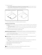
... then plug it is attached. NOTICE: Before touching anything inside your computer and attached devices are turned off now. Remove any static electricity that restrict access to a metal tray. NOTE: Your replacement board may or may not be attached to the system board. 8. Shut down the computer through the Start menu. 2. Disconnect any of the computer. Locate the password and RTC_RST jumpers on the password pins. 8. Removing...
... then plug it is attached. NOTICE: Before touching anything inside your computer and attached devices are turned off now. Remove any static electricity that restrict access to a metal tray. NOTE: Your replacement board may or may not be attached to the system board. 8. Shut down the computer through the Start menu. 2. Disconnect any of the computer. Locate the password and RTC_RST jumpers on the password pins. 8. Removing...
Service Manual
Page 22
... on the metal tray. Set the jumpers on the replacement system board so they are removed as one piece. b. Configure the settings of the computer, and then lift the board up and away. Replace any components and cables that you touch them on the existing board. Attach the computer stand. Connect your computer and devices to a metal tray, the board and the tray are...
... on the metal tray. Set the jumpers on the replacement system board so they are removed as one piece. b. Configure the settings of the computer, and then lift the board up and away. Replace any components and cables that you touch them on the existing board. Attach the computer stand. Connect your computer and devices to a metal tray, the board and the tray are...
Service Manual
Page 24
... Contents Page CAUTION: Safety Instructions Dell™ OptiPlex™ GX270 Service Manual General When Working Inside Your Computer Protecting Against Electrostatic Discharge Battery Disposal Use the following steps in instructions otherwise provided to you clean your computer. General l Do not attempt to service the computer yourself unless you must use an extension cable, use a 3-wire cable with properly grounded plugs. If you are a trained service technician. l To help...
... Contents Page CAUTION: Safety Instructions Dell™ OptiPlex™ GX270 Service Manual General When Working Inside Your Computer Protecting Against Electrostatic Discharge Battery Disposal Use the following steps in instructions otherwise provided to you clean your computer. General l Do not attempt to service the computer yourself unless you must use an extension cable, use a 3-wire cable with properly grounded plugs. If you are a trained service technician. l To help...

Service Manual
Page 25
... their antistatic packing material until you touch any connector pins. As you will never need to replace it, see "Replacing the Battery" in on the computer chassis to prevent damage from electrostatic discharge (ESD): l Do not remove components from your computer and devices, including the monitor, from the computer. If possible, use antistatic floor pads and workbench pads. l When transporting...
... their antistatic packing material until you touch any connector pins. As you will never need to replace it, see "Replacing the Battery" in on the computer chassis to prevent damage from electrostatic discharge (ESD): l Do not remove components from your computer and devices, including the monitor, from the computer. If possible, use antistatic floor pads and workbench pads. l When transporting...


