
Quick Reference Guide
Page 2
...personal injury, or death. Information in this document is strictly forbidden. All rights reserved. Trademarks used in this text: Dell, OptiPlex, and the DELL logo are registered trademarks of abbreviations and acronyms, see the Glossary in trademarks and trade names other than its own. ...of Intel Corporation. Models DCSM, DCNE September 2006 P/N YC764 Rev. Reproduction in any proprietary interest in the User's Guide. A01 Dell Inc. is subject to Microsoft® Windows® operating systems are not applicable. NOTICE: A NOTICE indicates either the entities ...
...personal injury, or death. Information in this document is strictly forbidden. All rights reserved. Trademarks used in this text: Dell, OptiPlex, and the DELL logo are registered trademarks of abbreviations and acronyms, see the Glossary in trademarks and trade names other than its own. ...of Intel Corporation. Models DCSM, DCNE September 2006 P/N YC764 Rev. Reproduction in any proprietary interest in the User's Guide. A01 Dell Inc. is subject to Microsoft® Windows® operating systems are not applicable. NOTICE: A NOTICE indicates either the entities ...
Quick Reference Guide
Page 3
... Tower Computer 17 Desktop Computer 19 Inside Your Computer 20 Mini Tower Computer 20 Desktop Computer 23 Setting Up Your Computer 26 Solving Problems 28 Dell Diagnostics 28 System Lights 31 Diagnostic Lights 32 Beep Codes 35 Resolving Software and Hardware Incompatibilities 36 Using Microsoft Windows XP System Restore 36 Reinstalling...
... Tower Computer 17 Desktop Computer 19 Inside Your Computer 20 Mini Tower Computer 20 Desktop Computer 23 Setting Up Your Computer 26 Solving Problems 28 Dell Diagnostics 28 System Lights 31 Diagnostic Lights 32 Beep Codes 35 Resolving Software and Hardware Incompatibilities 36 Using Microsoft Windows XP System Restore 36 Reinstalling...
Quick Reference Guide
Page 5
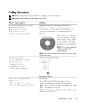
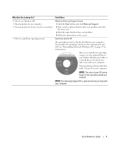
... User's Guide Microsoft® Windows® XP Help and Support Center 1 Click the Start button, then click Help and Support. 2 Click Dell User and System Guides, then click System Guides. 3 Click Dell Optiplex User's Guide. What Are You Looking For? • A diagnostic program for my computer • Drivers for your computer. Readme files...
... User's Guide Microsoft® Windows® XP Help and Support Center 1 Click the Start button, then click Help and Support. 2 Click Dell User and System Guides, then click System Guides. 3 Click Dell Optiplex User's Guide. What Are You Looking For? • A diagnostic program for my computer • Drivers for your computer. Readme files...
Quick Reference Guide
Page 6
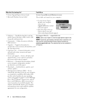
...Service Code to view the appropriate support site. DSS is necessary for your call when contacting technical support. • Solutions - support.dell.com articles from technicians, online courses, and NOTE: Select your region to direct your configuration. 6 Quick Reference Guide frequently asked questions...your computer and operating system and installs the updates appropriate for correct operation of your computer, you reinstall the operating system for Dell 3.5-inch USB floppy drives, Intel® Pentium® M processors, optical drives, and USB devices. If you should ...
...Service Code to view the appropriate support site. DSS is necessary for your call when contacting technical support. • Solutions - support.dell.com articles from technicians, online courses, and NOTE: Select your region to direct your configuration. 6 Quick Reference Guide frequently asked questions...your computer and operating system and installs the updates appropriate for correct operation of your computer, you reinstall the operating system for Dell 3.5-inch USB floppy drives, Intel® Pentium® M processors, optical drives, and USB devices. If you should ...
Quick Reference Guide
Page 7
To reinstall your computer. After you ordered. NOTE: The color of your CD varies based on your operating system, use Windows XP • Documentation for my computer • Documentation for devices (such as a modem) • How to reinstall drivers for instructions). Operating System CD The operating system is already installed on the operating system you reinstall your operating system, use the optional Drivers and Utilities CD (ResourceCD) to reinstall my operating system Windows Help and Support Center 1 Click the Start button and click Help and Support. 2 Type a word or ...
To reinstall your computer. After you ordered. NOTE: The color of your CD varies based on your operating system, use Windows XP • Documentation for my computer • Documentation for devices (such as a modem) • How to reinstall drivers for instructions). Operating System CD The operating system is already installed on the operating system you reinstall your operating system, use the optional Drivers and Utilities CD (ResourceCD) to reinstall my operating system Windows Help and Support Center 1 Click the Start button and click Help and Support. 2 Type a word or ...
Quick Reference Guide
Page 9
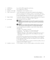
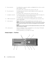
1 CD/DVD drive Insert a CD or DVD (if applicable) into this drive. 2 floppy drive Insert a floppy disk into this button to turn off . • Steady green - NOTICE: To avoid losing data, do not turn on page 31. 8 headphone connector Use the headphone connector to attach headphones and most kinds of the computer for devices that can help you connect occasionally, such as joysticks or cameras, or for devices that typically remain connected, such as a wake device in the Windows Device Manager. The computer is in your online User's Guide. See "Power Problems" in a power-saving ...
1 CD/DVD drive Insert a CD or DVD (if applicable) into this drive. 2 floppy drive Insert a floppy disk into this button to turn off . • Steady green - NOTICE: To avoid losing data, do not turn on page 31. 8 headphone connector Use the headphone connector to attach headphones and most kinds of the computer for devices that can help you connect occasionally, such as joysticks or cameras, or for devices that typically remain connected, such as a wake device in the Windows Device Manager. The computer is in your online User's Guide. See "Power Problems" in a power-saving ...
Quick Reference Guide
Page 10
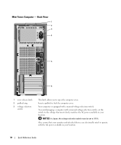
Insert a padlock to 115-V. NOTICE: In Japan, the voltage-selection switch must be set the switch to open the computer cover. To avoid damaging a computer with a manual voltage-selection switch, set to lock the computer cover. Mini Tower Computer - Back View 1 2 3 4 5 6 1 cover release latch 2 padlock ring 3 voltage selection switch This latch allows you to the voltage that your monitor and attached devices are electrically rated to operate with a manual voltage-selection switch. Also, ensure that most closely matches the AC power available in your location. Your ...
Insert a padlock to 115-V. NOTICE: In Japan, the voltage-selection switch must be set the switch to open the computer cover. To avoid damaging a computer with a manual voltage-selection switch, set to lock the computer cover. Mini Tower Computer - Back View 1 2 3 4 5 6 1 cover release latch 2 padlock ring 3 voltage selection switch This latch allows you to the voltage that your monitor and attached devices are electrically rated to operate with a manual voltage-selection switch. Also, ensure that most closely matches the AC power available in your location. Your ...
Quick Reference Guide
Page 11
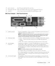
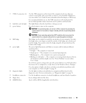
NOTE: The integrated parallel connector is recommended that the network cable has been securely attached. A good connection exists between a 100-Mbps network and the computer. • Off - On computers with a network adapter card, use the connector on the back panel of your online User's Guide. • Green - It is automatically disabled if the computer detects an installed card containing a parallel connector configured to be in a steady "on" state. A high volume of network traffic may make this connector. 5 back-panel connectors Plug serial, USB, and other end of the network ...
NOTE: The integrated parallel connector is recommended that the network cable has been securely attached. A good connection exists between a 100-Mbps network and the computer. • Off - On computers with a network adapter card, use the connector on the back panel of your online User's Guide. • Green - It is automatically disabled if the computer detects an installed card containing a parallel connector configured to be in a steady "on" state. A high volume of network traffic may make this connector. 5 back-panel connectors Plug serial, USB, and other end of the network ...
Quick Reference Guide
Page 12
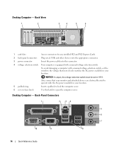
5 line-in connector 6 line-out connector 7 microphone connector 8 USB 2.0 connectors (4) 9 video connector 10 serial connector Use the blue line-in connector to attach a record/playback device such as a handheld device, to the serial port. Do not remove the cap. Use the pink microphone connector to attach a personal computer microphone for voice or musical input into the blue connector. Use the back USB connectors for serial connector 1. Plug the cable from your computer. On computers with a sound card, use the connector on the card. The default designation is on ...
5 line-in connector 6 line-out connector 7 microphone connector 8 USB 2.0 connectors (4) 9 video connector 10 serial connector Use the blue line-in connector to attach a record/playback device such as a handheld device, to the serial port. Do not remove the cap. Use the pink microphone connector to attach a personal computer microphone for voice or musical input into the blue connector. Use the back USB connectors for serial connector 1. Plug the cable from your computer. On computers with a sound card, use the connector on the card. The default designation is on ...
Quick Reference Guide
Page 13
NOTICE: If your operating system has ACPI enabled, when you press the power button the computer will perform an operating system shutdown. 4 Dell badge This badge can be rotated to match the orientation of your computer see "Diagnostic Lights" on page 32. 7 headphone connector Use the headphone connector ...
NOTICE: If your operating system has ACPI enabled, when you press the power button the computer will perform an operating system shutdown. 4 Dell badge This badge can be rotated to match the orientation of your computer see "Diagnostic Lights" on page 32. 7 headphone connector Use the headphone connector ...
Quick Reference Guide
Page 14
Back View 1 2 3 4 5 6 1 card slots Access connectors for any installed PCI and PCI Express Cards. 2 back-panel connectors Plug serial, USB, and other devices into the appropriate connector. 3 power connector Insert the power cable into this connector. 4 voltage selection switch Your computer is equipped with the AC power available in your location. 5 padlock ring Insert a padlock to lock the computer cover. 6 cover release latch Use this latch to open the computer cover. Also, ensure that most closely matches the AC power available in your location. To avoid ...
Back View 1 2 3 4 5 6 1 card slots Access connectors for any installed PCI and PCI Express Cards. 2 back-panel connectors Plug serial, USB, and other devices into the appropriate connector. 3 power connector Insert the power cable into this connector. 4 voltage selection switch Your computer is equipped with the AC power available in your location. 5 padlock ring Insert a padlock to lock the computer cover. 6 cover release latch Use this latch to open the computer cover. Also, ensure that most closely matches the AC power available in your location. To avoid ...

Quick Reference Guide
Page 15
A good connection exists between a 10-Mbps network and the computer. • Orange - The computer is not detecting a physical connection to the network adapter connector on the card. NOTE: Do not plug a telephone cable into a USB connector. For more information, see your computer to a network or broadband device, connect one end of your computer. Connect the other end of network traffic may make this light appear to ensure reliable operation. On computers with a sound card, use the connector on the back panel of a network cable to attach headphones and most speakers ...
A good connection exists between a 10-Mbps network and the computer. • Orange - The computer is not detecting a physical connection to the network adapter connector on the card. NOTE: Do not plug a telephone cable into a USB connector. For more information, see your computer to a network or broadband device, connect one end of your computer. Connect the other end of network traffic may make this light appear to ensure reliable operation. On computers with a sound card, use the connector on the back panel of a network cable to attach headphones and most speakers ...
Quick Reference Guide
Page 16
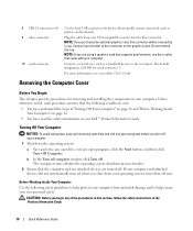
... covered by a cap. b In the Turn off computer window, click Turn off when you begin any open files, exit any of the procedures in your Dell™ Product Information Guide. CAUTION: Before you shut down the operating system: a Save and close any open programs, click the Start button, and then click...
... covered by a cap. b In the Turn off computer window, click Turn off when you begin any open files, exit any of the procedures in your Dell™ Product Information Guide. CAUTION: Before you shut down the operating system: a Save and close any open programs, click the Start button, and then click...
Quick Reference Guide
Page 17
Hold a card by its edges or by Dell is attached. Hold a component such as the metal at the back of the procedures in this type of the computer cover and pivot the cover ...
Hold a card by its edges or by Dell is attached. Hold a component such as the metal at the back of the procedures in this type of the computer cover and pivot the cover ...
Quick Reference Guide
Page 18
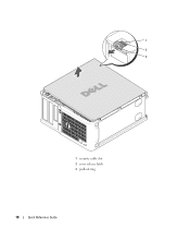
1 2 3 1 security cable slot 2 cover release latch 3 padlock ring 18 Quick Reference Guide
1 2 3 1 security cable slot 2 cover release latch 3 padlock ring 18 Quick Reference Guide
Quick Reference Guide
Page 19
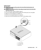
Desktop Computer CAUTION: Before you begin any of the procedures in this section, follow the safety instructions in "Before You Begin" on page 16. 2 If you have installed a padlock through the padlock ring on the back panel, remove the padlock. 3 Slide the cover release latch back as you lift the cover. 4 Pivot the cover up using the hinge tabs as leverage points. 5 Remove the cover from the hinge tabs and set it aside on a soft nonabrasive surface. 1 2 3 1 security cable slot 2 cover release latch 3 padlock ring Quick Reference Guide 19 CAUTION: To guard against electrical shock, always ...
Desktop Computer CAUTION: Before you begin any of the procedures in this section, follow the safety instructions in "Before You Begin" on page 16. 2 If you have installed a padlock through the padlock ring on the back panel, remove the padlock. 3 Slide the cover release latch back as you lift the cover. 4 Pivot the cover up using the hinge tabs as leverage points. 5 Remove the cover from the hinge tabs and set it aside on a soft nonabrasive surface. 1 2 3 1 security cable slot 2 cover release latch 3 padlock ring Quick Reference Guide 19 CAUTION: To guard against electrical shock, always ...
Quick Reference Guide
Page 20
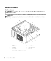
NOTICE: Be careful when opening the computer cover to ensure that you begin any of the procedures in this section, follow the safety instructions located in the Product Information Guide. Inside Your Computer Mini Tower Computer CAUTION: Before you do not accidentally disconnect cables from the electrical outlet before removing the computer cover. CAUTION: To avoid electrical shock, always unplug your computer from the system board. 3 2 1 4 5 6 7 1 CD/DVD drive 5 system board 2 floppy drive 6 heat sink assembly 3 power supply 7 hard drive 4 chassis manual voltage-selection ...
NOTICE: Be careful when opening the computer cover to ensure that you begin any of the procedures in this section, follow the safety instructions located in the Product Information Guide. Inside Your Computer Mini Tower Computer CAUTION: Before you do not accidentally disconnect cables from the electrical outlet before removing the computer cover. CAUTION: To avoid electrical shock, always unplug your computer from the system board. 3 2 1 4 5 6 7 1 CD/DVD drive 5 system board 2 floppy drive 6 heat sink assembly 3 power supply 7 hard drive 4 chassis manual voltage-selection ...
Quick Reference Guide
Page 22
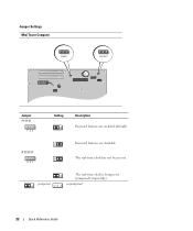
RTCRST 3 2 1 Password features are enabled (default). jumpered The real-time clock is being reset (jumpered temporarily). The real-time clock has not been reset. unjumpered 22 Quick Reference Guide Jumper Settings Mini Tower Computer PSWD RTCRST Jumper PSWD 1 2 3 Setting Description Password features are disabled.
RTCRST 3 2 1 Password features are enabled (default). jumpered The real-time clock is being reset (jumpered temporarily). The real-time clock has not been reset. unjumpered 22 Quick Reference Guide Jumper Settings Mini Tower Computer PSWD RTCRST Jumper PSWD 1 2 3 Setting Description Password features are disabled.

Quick Reference Guide
Page 23
NOTICE: Be careful when opening the computer cover to ensure that you begin any of the procedures in this section, follow the safety instructions in the Product Information Guide. CAUTION: To avoid electrical shock, always unplug your computer from the system board. 2 1 3 4 6 5 1 drive bay (CD/DVD, floppy, 4 card slots and hard drive) 2 power supply 5 heat sink assembly 3 system board 6 front I/O panel Quick Reference Guide 23 Desktop Computer CAUTION: Before you do not accidentally disconnect cables from the electrical outlet before removing the computer cover.
NOTICE: Be careful when opening the computer cover to ensure that you begin any of the procedures in this section, follow the safety instructions in the Product Information Guide. CAUTION: To avoid electrical shock, always unplug your computer from the system board. 2 1 3 4 6 5 1 drive bay (CD/DVD, floppy, 4 card slots and hard drive) 2 power supply 5 heat sink assembly 3 system board 6 front I/O panel Quick Reference Guide 23 Desktop Computer CAUTION: Before you do not accidentally disconnect cables from the electrical outlet before removing the computer cover.
Quick Reference Guide
Page 25
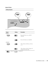
unjumpered Quick Reference Guide 25 The real-time clock has not been reset. jumpered The real-time clock is being reset (jumpered temporarily). RTCRST 3 2 1 Password features are enabled (default). Jumper Settings Desktop Computer PSWD RTCRST Jumper PSWD 1 2 3 Setting Description Password features are disabled.
unjumpered Quick Reference Guide 25 The real-time clock has not been reset. jumpered The real-time clock is being reset (jumpered temporarily). RTCRST 3 2 1 Password features are enabled (default). Jumper Settings Desktop Computer PSWD RTCRST Jumper PSWD 1 2 3 Setting Description Password features are disabled.
