E-Family Re-Image Guide
Page 5
...Solo & Celeron M - Display Port - WiMAX - Broadcom Unified Security Hub (USH) - Free Fall Sensor on non E-Family or previous Dell products. Latitude On / Precision On - eSATA - Graphics controller (Intel, nVidia and AMD) - Webcam - Wireless LAN - applies to E-Family 1st generation only o...To" Guide 2.2 E-Family New Features & Image Impact Dell E-Family systems feature new hardware technologies which require a new software stack, drivers, and / or applications. Intel Turbo Boost - Network LoM (Intel and Broadcom) - USB 3.0 (Only M6500) - Intel AMT (Intel Active ...
...Solo & Celeron M - Display Port - WiMAX - Broadcom Unified Security Hub (USH) - Free Fall Sensor on non E-Family or previous Dell products. Latitude On / Precision On - eSATA - Graphics controller (Intel, nVidia and AMD) - Webcam - Wireless LAN - applies to E-Family 1st generation only o...To" Guide 2.2 E-Family New Features & Image Impact Dell E-Family systems feature new hardware technologies which require a new software stack, drivers, and / or applications. Intel Turbo Boost - Network LoM (Intel and Broadcom) - USB 3.0 (Only M6500) - Intel AMT (Intel Active ...
E-Family Re-Image Guide
Page 6
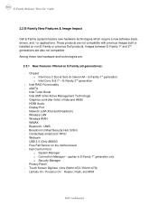
Intel vPro (AMT 6.0) - Connection Manager removed from DCP - Dell Backup & Recovery Manager - Dell Manageability Package Dell Confidential DDR3 Memory - Multi-touch Touchpad - Chipset o Core i5 & i7 i5 Dual Core CPUs that include updated integrated ... Turbo Boost - Noise Cancelling Digital Array Mics and Light Sensitive Webcam for VOIP and Video Conferencing - Latitude On / Precision On - Reader and Flash - E-Family Reimage "How-To" Guide 2.2.2 New Features Specific to E-Family 2nd Generation - New BIOS architecture - USB 3.0 - Free Fall Sensor on the motherboard -
Intel vPro (AMT 6.0) - Connection Manager removed from DCP - Dell Backup & Recovery Manager - Dell Manageability Package Dell Confidential DDR3 Memory - Multi-touch Touchpad - Chipset o Core i5 & i7 i5 Dual Core CPUs that include updated integrated ... Turbo Boost - Noise Cancelling Digital Array Mics and Light Sensitive Webcam for VOIP and Video Conferencing - Latitude On / Precision On - Reader and Flash - E-Family Reimage "How-To" Guide 2.2.2 New Features Specific to E-Family 2nd Generation - New BIOS architecture - USB 3.0 - Free Fall Sensor on the motherboard -
E-Family Re-Image Guide
Page 8
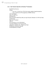
...Personal Area Network Adapter (UWB / WPAN) 12. E-Family 1st generation only • Security Manager Latitude On & Precision On Reader & Flash Backup & Recovery Manager Dell Confidential Intel vPro or AMT 17. XP (32 & 64-Bit ) only 20. Actual system configurations may vary...Installation Software Hardware Intel Core 2 Duo & Solo & Celeron M - Dell Control Point Security Driver Pack. 10. Mobile Broadband Wireless Wide Area Network Adapter (WWAN) 13. Touch Pad/Track Stick/Pointer 14. USB 3.0 18. Dell Desktop System Software 3. Intel Storage: 5. Free Fall Sensor 15. ...
...Personal Area Network Adapter (UWB / WPAN) 12. E-Family 1st generation only • Security Manager Latitude On & Precision On Reader & Flash Backup & Recovery Manager Dell Confidential Intel vPro or AMT 17. XP (32 & 64-Bit ) only 20. Actual system configurations may vary...Installation Software Hardware Intel Core 2 Duo & Solo & Celeron M - Dell Control Point Security Driver Pack. 10. Mobile Broadband Wireless Wide Area Network Adapter (WWAN) 13. Touch Pad/Track Stick/Pointer 14. USB 3.0 18. Dell Desktop System Software 3. Intel Storage: 5. Free Fall Sensor 15. ...
E-Family Re-Image Guide
Page 10
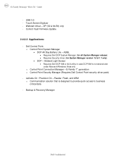
Touch Screen Digitizer - Latitude On / Precision On - Dell Control Point: o Control Point System Manager • DCP All Day Battery Life - E-Family 1st generation o Control Point Security Manager (Requires Dell Control Point security driver pack) - Reader, Flash, and ARM o...and under Microsoft Windows Vista only o Control Point Connection Manager - Webcam driver - Backup & Recovery Manager Dell Confidential XP (32 & 64-Bit) only - USB 3.0 - ADBL • Requires Dell DCP System Manager (for all System Manager release) • Requires Security driver (for System Manager version ...
Touch Screen Digitizer - Latitude On / Precision On - Dell Control Point: o Control Point System Manager • DCP All Day Battery Life - E-Family 1st generation o Control Point Security Manager (Requires Dell Control Point security driver pack) - Reader, Flash, and ARM o...and under Microsoft Windows Vista only o Control Point Connection Manager - Webcam driver - Backup & Recovery Manager Dell Confidential XP (32 & 64-Bit) only - USB 3.0 - ADBL • Requires Dell DCP System Manager (for all System Manager release) • Requires Security driver (for System Manager version ...
E-Family Re-Image Guide
Page 22
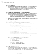
... to: o Discover computing assets on Dell's driver & downloads support web site (support.dell.com) under the "Applications" section posted on Dell's driver & downloads support web site (support.dell.com) 2.6.18 Modem (Not applicable to installing the AMT drivers: o Intel Mobile Chipset driver o Intel 825xx Gigabit Platform...- The AMT drivers are being installed prior to Dell Precision M6400/6500) - Microsoft XP 32 & 64-Bit, Vista 32 & 64-Bit, and Win7 32 & 64-Bit Operating Systems do not include the USB 3.0 driver. If Dell Control Point Connection Manager module is installed, the ...
... to: o Discover computing assets on Dell's driver & downloads support web site (support.dell.com) under the "Applications" section posted on Dell's driver & downloads support web site (support.dell.com) 2.6.18 Modem (Not applicable to installing the AMT drivers: o Intel Mobile Chipset driver o Intel 825xx Gigabit Platform...- The AMT drivers are being installed prior to Dell Precision M6400/6500) - Microsoft XP 32 & 64-Bit, Vista 32 & 64-Bit, and Win7 32 & 64-Bit Operating Systems do not include the USB 3.0 driver. If Dell Control Point Connection Manager module is installed, the ...
E-Family Re-Image Guide
Page 27
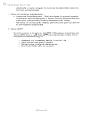
...an industry standard interface. A few of the key benefits of the connectors on the Dell Drivers and Download page 7. It can use the scheduling option to keep their system up to six times faster than USB 2.0 and IEEE 1394 o Robust and user friendly external connection o High performance, cost...tool is the Client System Update application? What is designed to allow users to -date with either an eSATA device or a USB device. Alternatively, end users can interface with the systems software released by Dell 8. E-Family Reimage "How-To" Guide utility first after re-imaging your system.
...an industry standard interface. A few of the key benefits of the connectors on the Dell Drivers and Download page 7. It can use the scheduling option to keep their system up to six times faster than USB 2.0 and IEEE 1394 o Robust and user friendly external connection o High performance, cost...tool is the Client System Update application? What is designed to allow users to -date with either an eSATA device or a USB device. Alternatively, end users can interface with the systems software released by Dell 8. E-Family Reimage "How-To" Guide utility first after re-imaging your system.

Replacing the System Board
Page 2
...the initialization is complete, the computer shuts down. 8 Reconnect the network cable and the mass storage devices like hard drives or USB flash keys. 5 Connect the AC adapter and turn on replacing the system board, see your computer documentation for your computer may...process is not reversible. If you make the wrong selection, your computer. An initialization screen is missing, damaged, or otherwise illegible, contact Dell to select the appropriate configuration for contact information). 3 Replace the bottom access panel. You should . 6 Enter the configuration-mode number that...
...the initialization is complete, the computer shuts down. 8 Reconnect the network cable and the mass storage devices like hard drives or USB flash keys. 5 Connect the AC adapter and turn on replacing the system board, see your computer documentation for your computer may...process is not reversible. If you make the wrong selection, your computer. An initialization screen is missing, damaged, or otherwise illegible, contact Dell to select the appropriate configuration for contact information). 3 Replace the bottom access panel. You should . 6 Enter the configuration-mode number that...
Setup and Quick Reference Guide
Page 8
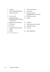
5 keyboard 6 volume control buttons 7 Dell ControlPoint (DCP) button 8 power button 9 USB connectors (2) 10 audio (line-out) and microphone (line-in) connectors 11 smart card slot 12 IEEE 1394a connector 13 wireless switch and 14 speaker Dell™ Wi-Fi Catcher™ Network Locator button 15 fingerprint reader (optional) 16 media bay 17 PC Card slot 18 contactless smart-card-reader 19 track stick 20 display latch release 21 track stick buttons/touch pad buttons 22 touch pad 23 speaker 24 device status lights 25 ambient light sensor 8 About Your Computer
5 keyboard 6 volume control buttons 7 Dell ControlPoint (DCP) button 8 power button 9 USB connectors (2) 10 audio (line-out) and microphone (line-in) connectors 11 smart card slot 12 IEEE 1394a connector 13 wireless switch and 14 speaker Dell™ Wi-Fi Catcher™ Network Locator button 15 fingerprint reader (optional) 16 media bay 17 PC Card slot 18 contactless smart-card-reader 19 track stick 20 display latch release 21 track stick buttons/touch pad buttons 22 touch pad 23 speaker 24 device status lights 25 ambient light sensor 8 About Your Computer
Setup and Quick Reference Guide
Page 9
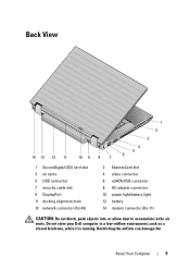
... 7 security cable slot 9 DisplayPort 11 docking alignment mark 13 network connector (RJ-45) 2 ExpressCard slot 4 video connector 6 eSATA/USB connector 8 AC adapter connector 10 power light/battery light 12 battery 14 modem connector (RJ-11) CAUTION: Do not block, push objects into, or allow ...
... 7 security cable slot 9 DisplayPort 11 docking alignment mark 13 network connector (RJ-45) 2 ExpressCard slot 4 video connector 6 eSATA/USB connector 8 AC adapter connector 10 power light/battery light 12 battery 14 modem connector (RJ-11) CAUTION: Do not block, push objects into, or allow ...

Setup and Quick Reference Guide
Page 14
2 Connect the network cable. 3 Connect USB devices, such as a mouse or keyboard. 4 Connect IEEE 1394 devices, such as a DVD player. 14 Setting Up Your Computer
2 Connect the network cable. 3 Connect USB devices, such as a mouse or keyboard. 4 Connect IEEE 1394 devices, such as a DVD player. 14 Setting Up Your Computer

Setup and Quick Reference Guide
Page 25
Ports and Connectors (continued) Mini-Card support (internal expansion slots) Optical drive bay Modem Network adapter USB, eSATA Video Communications Network adapter Wireless Mobile Broadband Global Positioning System (GPS) one dedicated Half-Mini-Card slot for wireless local area network (WLAN) one dedicated...2 A shared power for external device one USB 2.0/eSATA connector with up to 2 A shared power for external device DisplayPort supports HDMI, DVI, dual-link DVI, and VGA via dongle 10/100/1000 Ethernet LAN on system board WLAN Mobile Broadband Bluetooth® wireless technology WI-MAX ...
Ports and Connectors (continued) Mini-Card support (internal expansion slots) Optical drive bay Modem Network adapter USB, eSATA Video Communications Network adapter Wireless Mobile Broadband Global Positioning System (GPS) one dedicated Half-Mini-Card slot for wireless local area network (WLAN) one dedicated...2 A shared power for external device one USB 2.0/eSATA connector with up to 2 A shared power for external device DisplayPort supports HDMI, DVI, dual-link DVI, and VGA via dongle 10/100/1000 Ethernet LAN on system board WLAN Mobile Broadband Bluetooth® wireless technology WI-MAX ...

Setup and Quick Reference Guide
Page 41
... be enabled or disabled in BIOS setup. A PARAMETER OUT OF RANGE MAY OR M A Y N O T I N D I C A T E A P O T E N T I A L H A R D D R I N T E R R U P T - CMOS CHECKSUM ERROR - See your Service Manual at support.dell.com). HA R D -DISK DRIVE FAILURE - N O T I M E R T I C K I V E P R O B L E M - USB OVER CURRENT ERROR - Troubleshooting 41 FOR HELP IN RESOLVING THIS PROBLEM, PLEASE NOTE THIS C H E C K P O I N T A N D C O N T A C T D E L L TE C H N I L U R E - Processor fan failure. Check cables, swap hard disks...
... be enabled or disabled in BIOS setup. A PARAMETER OUT OF RANGE MAY OR M A Y N O T I N D I C A T E A P O T E N T I A L H A R D D R I N T E R R U P T - CMOS CHECKSUM ERROR - See your Service Manual at support.dell.com). HA R D -DISK DRIVE FAILURE - N O T I M E R T I C K I V E P R O B L E M - USB OVER CURRENT ERROR - Troubleshooting 41 FOR HELP IN RESOLVING THIS PROBLEM, PLEASE NOTE THIS C H E C K P O I N T A N D C O N T A C T D E L L TE C H N I L U R E - Processor fan failure. Check cables, swap hard disks...

Setup and Quick Reference Guide
Page 69
... Internet, 16 network, 15 network cable, 14 USB devices, 14 contacting Dell, 59, 65 D Dell contacting, 59, 65 software updates, 49 Support Utility, 49 Dell (continued) technical support and customer service, 60 Technical Update Service, 48 Dell Diagnostics, 42 starting from the Drivers and Utilities media..., 43 starting from your hard drive, 43 Dell Factory Image Restore, 56 Dell Technology Guide, 68 DellConnect, 60 diagnostics beep codes, 34 Dell, 42 power lights, 9, 33 documentation, 67 Dell Technology Guide, 68 Service Manual, 68 drivers, 51 Drivers and Utilities...
... Internet, 16 network, 15 network cable, 14 USB devices, 14 contacting Dell, 59, 65 D Dell contacting, 59, 65 software updates, 49 Support Utility, 49 Dell (continued) technical support and customer service, 60 Technical Update Service, 48 Dell Diagnostics, 42 starting from the Drivers and Utilities media..., 43 starting from your hard drive, 43 Dell Factory Image Restore, 56 Dell Technology Guide, 68 DellConnect, 60 diagnostics beep codes, 34 Dell, 42 power lights, 9, 33 documentation, 67 Dell Technology Guide, 68 Service Manual, 68 drivers, 51 Drivers and Utilities...

Service Manual
Page 3
... the coin-cell battery (see Removing the Processor Heat Sink). Pull out on the top, left corner of the base assembly to release the DC, USB, and display connectors. 26. Remove the modem cable from the system board. Remove the processor heat sink (see Removing the Coin-Cell Battery). 17. Disconnect...
... the coin-cell battery (see Removing the Processor Heat Sink). Pull out on the top, left corner of the base assembly to release the DC, USB, and display connectors. 26. Remove the modem cable from the system board. Remove the processor heat sink (see Removing the Coin-Cell Battery). 17. Disconnect...
Service Manual
Page 47
... Rest Assembly). 15. Remove the palm rest assembly (see Removing the Bottom of the base assembly to Contents Page DC Power Cable Dell Precision™ Service Manual Removing the DC Power Cable Replacing the DC Power Cable Removing the DC Power Cable CAUTION: Before working inside your... heat sink (see Removing the Hinge Covers). 8. Remove three M2.5 x 5-mm screws labeled with your computer. Back to release the DC power, USB, and display connectors. 19. Remove the battery (see Removing the Keyboard). 10. Remove the keyboard (see Removing the Battery). 4. Remove the DC ...
... Rest Assembly). 15. Remove the palm rest assembly (see Removing the Bottom of the base assembly to Contents Page DC Power Cable Dell Precision™ Service Manual Removing the DC Power Cable Replacing the DC Power Cable Removing the DC Power Cable CAUTION: Before working inside your... heat sink (see Removing the Hinge Covers). 8. Remove three M2.5 x 5-mm screws labeled with your computer. Back to release the DC power, USB, and display connectors. 19. Remove the battery (see Removing the Keyboard). 10. Remove the keyboard (see Removing the Battery). 4. Remove the DC ...

Service Manual
Page 54
... serial connectors fit into the base, then connect the top right of the system board to release the DC, USB, and serial connectors. 27. Replace the five M2.5 x 4-mm screws to the system board. 6. Replace the PC card cage by gently pushing the inward end ... of the system board into the base of the cage down over its mounting bracket. Connect the I /O board connector. 3. Pull out on www.dell.com at: www.dell.com/regulatory_compliance. Replace the system board in the opposite order of the computer. 1 SD cable and Express card cage cable connectors 2 DC power cable...
... serial connectors fit into the base, then connect the top right of the system board to release the DC, USB, and serial connectors. 27. Replace the five M2.5 x 4-mm screws to the system board. 6. Replace the PC card cage by gently pushing the inward end ... of the system board into the base of the cage down over its mounting bracket. Connect the I /O board connector. 3. Pull out on www.dell.com at: www.dell.com/regulatory_compliance. Replace the system board in the opposite order of the computer. 1 SD cable and Express card cage cable connectors 2 DC power cable...


