Setup and Quick Reference Guide
Page 38
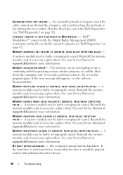
... keypads, check the cable connection. Restart the computer, and avoid touching the keyboard or keys during the boot routine. Reinstall the memory modules and, if necessary, replace them. A memory module may be played (see "Dell Diagnostics" on the file, so the file cannot be faulty or improperly seated. A memory module may be faulty...
... keypads, check the cable connection. Restart the computer, and avoid touching the keyboard or keys during the boot routine. Reinstall the memory modules and, if necessary, replace them. A memory module may be played (see "Dell Diagnostics" on the file, so the file cannot be faulty or improperly seated. A memory module may be faulty...

Setup and Quick Reference Guide
Page 40
... A chip on page 42). Run the System Memory tests and the Keyboard Controller test in the table, see "Dell Diagnostics" on the system board may be malfunctioning, or a memory module...P E C T E D I N T E R R U P T I B L E . X : \ I S N O T A C C E S S I N P R O T E C T E D M O D E - The operating system cannot find a specific track on page 42). If the message reappears, contact Dell (see "Dell Diagnostics" on the hard drive. TI M E - D A Y N O T S E T - Replace the battery, or connect the computer to charge the battery. Run the System Set tests in the system setup program does not...
... A chip on page 42). Run the System Memory tests and the Keyboard Controller test in the table, see "Dell Diagnostics" on the system board may be malfunctioning, or a memory module...P E C T E D I N T E R R U P T I B L E . X : \ I S N O T A C C E S S I N P R O T E C T E D M O D E - The operating system cannot find a specific track on page 42). If the message reappears, contact Dell (see "Dell Diagnostics" on the hard drive. TI M E - D A Y N O T S E T - Replace the battery, or connect the computer to charge the battery. Run the System Set tests in the system setup program does not...

Setup and Quick Reference Guide
Page 41
... complete the start test (see your Service Manual at support.dell.com or see "Contacting Dell" on page 65 for assistance). CMOS CHECKSUM ERROR - See your Service Manual at support.dell.com. HA R D -D I S K D R I V E R E A D F A I C A L S U P P O R T - Keyboard failure or keyboard cable loose. A chip on the system board might be ...see "Contacting Dell" on hard drive, or the hard drive cable is loose, or no bootable device exists. • If the hard drive is correct see "Contacting Dell" on page 65 for assistance. Replace battery. Replace processor fan. KEYBOARD FAILURE -...
... complete the start test (see your Service Manual at support.dell.com or see "Contacting Dell" on page 65 for assistance). CMOS CHECKSUM ERROR - See your Service Manual at support.dell.com. HA R D -D I S K D R I V E R E A D F A I C A L S U P P O R T - Keyboard failure or keyboard cable loose. A chip on the system board might be ...see "Contacting Dell" on hard drive, or the hard drive cable is loose, or no bootable device exists. • If the hard drive is correct see "Contacting Dell" on page 65 for assistance. Replace battery. Replace processor fan. KEYBOARD FAILURE -...

Service Manual
Page 4
... latches. 1. Install the modem cable. Replace the keyboard and LED cover (see Replacing the SD Card Reader). 7. Replace the fan (see Replacing the Modular Drive). 23. Replace the card in the WLAN/WiMax slot, if it was present (see Replacing a WLAN Card). 19. Replace the modular drive (see Replacing the Fan). 16. Replace the hard drive (see Replacing a WWAN Card). 18.
... latches. 1. Install the modem cable. Replace the keyboard and LED cover (see Replacing the SD Card Reader). 7. Replace the fan (see Replacing the Modular Drive). 23. Replace the card in the WLAN/WiMax slot, if it was present (see Replacing a WLAN Card). 19. Replace the modular drive (see Replacing the Fan). 16. Replace the hard drive (see Replacing a WWAN Card). 18.
Service Manual
Page 8
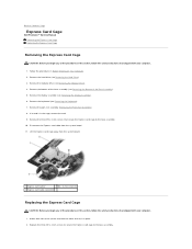
...the three M2 x 3-mm screws that secure the Express card cage to the base assembly. Remove the hard drive (see Removing the Keyboard). 7. Remove the keyboard (see Removing the Hard Drive). 3. Remove the bottom of the base assembly (see Removing the Display Assembly). 6. Attach one side of...). 5. Remove the modular drive (see Removing the Modular Drive). 4. Back to Contents Page Express Card Cage Dell Precision™ Service Manual Removing the Express Card Cage Replacing the Express Card Cage Removing the Express Card Cage CAUTION: Before you begin any of the procedures in this ...
...the three M2 x 3-mm screws that secure the Express card cage to the base assembly. Remove the hard drive (see Removing the Keyboard). 7. Remove the keyboard (see Removing the Hard Drive). 3. Remove the bottom of the base assembly (see Removing the Display Assembly). 6. Attach one side of...). 5. Remove the modular drive (see Removing the Modular Drive). 4. Back to Contents Page Express Card Cage Dell Precision™ Service Manual Removing the Express Card Cage Replacing the Express Card Cage Removing the Express Card Cage CAUTION: Before you begin any of the procedures in this ...

Service Manual
Page 9
Back to the system board. 4. Reconnect the Express card cable to Contents Page Replace the bottom of the Base Assembly). 8. Replace the modular drive (see Replacing the Bottom of the base assembly (see Replacing the Modular Drive). 9. Replace the display assembly (see Replacing the Keyboard). 6. Follow the procedure After Working on Your Computer. Replace the keyboard (see Replacing the Display Assembly). 7. Replace the hard drive (see Replacing the Hard Drive). 10. 3. Replace the palm rest assembly (Replacing the Palm Rest Assembly). 5.
Back to the system board. 4. Reconnect the Express card cable to Contents Page Replace the bottom of the Base Assembly). 8. Replace the modular drive (see Replacing the Bottom of the base assembly (see Replacing the Modular Drive). 9. Replace the display assembly (see Replacing the Keyboard). 6. Follow the procedure After Working on Your Computer. Replace the keyboard (see Replacing the Display Assembly). 7. Replace the hard drive (see Replacing the Hard Drive). 10. 3. Replace the palm rest assembly (Replacing the Palm Rest Assembly). 5.

Service Manual
Page 35
... two M2 x 3-mm screws at an angle to remove the keyboard from its connector. 1 keyboard 2 blue pull tab 3 M2 x 3-mm screw (2) Replacing the Keyboard CAUTION: Before you begin any of the keyboard. Back to Contents Page Keyboard Dell Precision™ Service Manual Removing the Keyboard Replacing the Keyboard Removing the Keyboard CAUTION: Before you begin any of the procedures in this section...
... two M2 x 3-mm screws at an angle to remove the keyboard from its connector. 1 keyboard 2 blue pull tab 3 M2 x 3-mm screw (2) Replacing the Keyboard CAUTION: Before you begin any of the keyboard. Back to Contents Page Keyboard Dell Precision™ Service Manual Removing the Keyboard Replacing the Keyboard Removing the Keyboard CAUTION: Before you begin any of the procedures in this section...

Service Manual
Page 36
1 keyboard connector 2 tabs (5) 3 M2 x 3-mm screw (2) 4. Close the display and turn the computer over. 6. Follow the procedure After Working on Your Computer. Back to Contents Page Replace the LED cover (see Replacing the LED Cover). 5.
1 keyboard connector 2 tabs (5) 3 M2 x 3-mm screw (2) 4. Close the display and turn the computer over. 6. Follow the procedure After Working on Your Computer. Back to Contents Page Replace the LED cover (see Replacing the LED Cover). 5.
Service Manual
Page 44
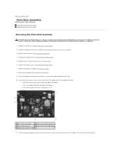
... the fan and the two heat sinks (see Display Assembly). 8. Remove the display assembly (see Heat Sinks). 6. Remove the keyboard (see Removing the Modular Drive). 5. For additional safety best practices information, see Removing the Hinge Covers). 7. Remove the modular drive (see... the hinge covers (see the Regulatory Compliance Homepage on Your Computer. 2. Back to Contents Page Palm Rest Assembly Dell Precision™ Service Manual Removing the Palm Rest Assembly Replacing the Palm Rest Assembly Removing the Palm Rest Assembly CAUTION: Before working inside your computer.
... the fan and the two heat sinks (see Display Assembly). 8. Remove the display assembly (see Heat Sinks). 6. Remove the keyboard (see Removing the Modular Drive). 5. For additional safety best practices information, see Removing the Hinge Covers). 7. Remove the modular drive (see... the hinge covers (see the Regulatory Compliance Homepage on Your Computer. 2. Back to Contents Page Palm Rest Assembly Dell Precision™ Service Manual Removing the Palm Rest Assembly Replacing the Palm Rest Assembly Removing the Palm Rest Assembly CAUTION: Before working inside your computer.
Service Manual
Page 46
... lower and snap the left corner, marked with an "S" 6. 3. Turn the computer topside up and replace the keyboard (see Replacing the Hard Drive). 20. Replace the discrete graphics heat sink (see Replacing the Hinge Covers). 17. Replace the hinge covers (see Replacing the Discrete Graphics Heat Sink). 11. Lower the palm rest onto the computer ensuring that...
... lower and snap the left corner, marked with an "S" 6. 3. Turn the computer topside up and replace the keyboard (see Replacing the Hard Drive). 20. Replace the discrete graphics heat sink (see Replacing the Hinge Covers). 17. Replace the hinge covers (see Replacing the Discrete Graphics Heat Sink). 11. Lower the palm rest onto the computer ensuring that...
Service Manual
Page 47
... of the base assembly (see Removing the Bottom of the base assembly to Contents Page DC Power Cable Dell Precision™ Service Manual Removing the DC Power Cable Replacing the DC Power Cable Removing the DC Power Cable CAUTION: Before working inside your computer. Remove the processor...see Removing the Display Assembly). 9. Remove the display assembly (see Removing the Modular Drive). 7. Remove the keyboard (see Removing the Fan). 11. Remove the fan (see Removing the Keyboard). 10. Remove the discrete graphics heat sink (see Removing the Express Card Cage). 16. Remove the ...
... of the base assembly (see Removing the Bottom of the base assembly to Contents Page DC Power Cable Dell Precision™ Service Manual Removing the DC Power Cable Replacing the DC Power Cable Removing the DC Power Cable CAUTION: Before working inside your computer. Remove the processor...see Removing the Display Assembly). 9. Remove the display assembly (see Removing the Modular Drive). 7. Remove the keyboard (see Removing the Fan). 11. Remove the fan (see Removing the Keyboard). 10. Remove the discrete graphics heat sink (see Removing the Express Card Cage). 16. Remove the ...
Service Manual
Page 48
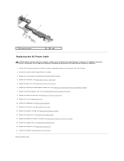
...dell.com at: www.dell.com/regulatory_compliance. 1. Replace the card cage (see Replacing the Discrete Graphics Heat Sink). 8. Replace the discrete graphics heat sink (see Replacing the Express Card Cage). 5. Replace the modular drive (see Replacing the Hard Drive). 17. Replace the hard drive (see Replacing... information that shipped with the base. 2. Replace the speaker grill and fingerprint reader cover (see Replacing the Keyboard). 11. Replace the keyboard (see Replacing the Right Speaker Grill and Fingerprint Reader). 7. Replace the bottom of the Base Assembly). 15....
...dell.com at: www.dell.com/regulatory_compliance. 1. Replace the card cage (see Replacing the Discrete Graphics Heat Sink). 8. Replace the discrete graphics heat sink (see Replacing the Express Card Cage). 5. Replace the modular drive (see Replacing the Hard Drive). 17. Replace the hard drive (see Replacing... information that shipped with the base. 2. Replace the speaker grill and fingerprint reader cover (see Replacing the Keyboard). 11. Replace the keyboard (see Replacing the Right Speaker Grill and Fingerprint Reader). 7. Replace the bottom of the Base Assembly). 15....
Service Manual
Page 49
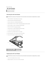
... Base Assembly). 5. Remove the hard drive (see Removing the Modular Drive). 4. Remove the keyboard (see Removing the Display Assembly). 6. Replace the two M2.5 x 3-mm screws to Contents Page SD Card Reader Dell Precision™ Service Manual Removing the SD Card Reader Replacing the SD Card Reader Removing the SD Card Reader CAUTION: Before you begin...
... Base Assembly). 5. Remove the hard drive (see Removing the Modular Drive). 4. Remove the keyboard (see Removing the Display Assembly). 6. Replace the two M2.5 x 3-mm screws to Contents Page SD Card Reader Dell Precision™ Service Manual Removing the SD Card Reader Replacing the SD Card Reader Removing the SD Card Reader CAUTION: Before you begin...

Service Manual
Page 50
Replace the modular drive (see Replacing the Bottom of the base assembly (see Replacing the Modular Drive). 8. Replace the bottom of the Base Assembly). 10. Replace the display assembly (see Replacing the Hard Drive). 9. Follow the procedure After Working on Your Computer. Back to the system board. 4. Replace the palm rest assembly (Replacing the Palm Rest Assembly). 5. Replace the hard drive (see Replacing the Display Assembly). 7. 3. Connect the SD card reader cable to Contents Page Replace the keyboard (see Replacing the Keyboard). 6.
Replace the modular drive (see Replacing the Bottom of the base assembly (see Replacing the Modular Drive). 8. Replace the bottom of the Base Assembly). 10. Replace the display assembly (see Replacing the Hard Drive). 9. Follow the procedure After Working on Your Computer. Back to the system board. 4. Replace the palm rest assembly (Replacing the Palm Rest Assembly). 5. Replace the hard drive (see Replacing the Display Assembly). 7. 3. Connect the SD card reader cable to Contents Page Replace the keyboard (see Replacing the Keyboard). 6.
Service Manual
Page 51
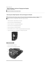
... or install one. 1. Remove the hard drive (see Removing the Keyboard). 6. NOTE: If you do not have a fingerprint reader, ignore steps to Contents Page Right Speaker Grill and Fingerprint Reader Dell Precision™ Service Manual Removing the Right Speaker Grill and Fingerprint Reader Replacing the Right Speaker Grill and Fingerprint Reader Removing the Right...
... or install one. 1. Remove the hard drive (see Removing the Keyboard). 6. NOTE: If you do not have a fingerprint reader, ignore steps to Contents Page Right Speaker Grill and Fingerprint Reader Dell Precision™ Service Manual Removing the Right Speaker Grill and Fingerprint Reader Replacing the Right Speaker Grill and Fingerprint Reader Removing the Right...
Service Manual
Page 52
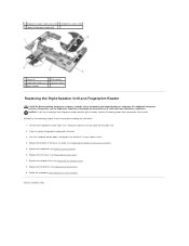
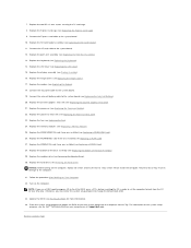
... LED Cover). 7. Follow the procedure After Working on www.dell.com at: www.dell.com/regulatory_compliance. Snap the speaker/fingerprint reader grill into the palm rest. 2. Replace the LED cover (see Replacing the Modular Drive). 8. Replace the hard drive (see Replacing the Keyboard). 6. Hard drives are installing a new fingerprint reader/speaker grill assembly, remove the backing paper...
... LED Cover). 7. Follow the procedure After Working on www.dell.com at: www.dell.com/regulatory_compliance. Snap the speaker/fingerprint reader grill into the palm rest. 2. Replace the LED cover (see Replacing the Modular Drive). 8. Replace the hard drive (see Replacing the Keyboard). 6. Hard drives are installing a new fingerprint reader/speaker grill assembly, remove the backing paper...
Service Manual
Page 55
...13. Enter the system setup program to the system board (see the Dell™ Technology Guide on your computer on at support.dell.com. Replace the palm rest assembly (see Replacing the Hinge Covers). 17. NOTICE: Before turning on the new system board...program, see Replacing the Coin-Cell Battery). 20. Replace the keyboard (see Removing the Modular Drive). 30. Replace the modular drive (see Replacing the Keyboard). 14. Replace the processor (see Replacing the Express Card Cage). 9. Replace the Express card cage (see Replacing the Processor Module). 22. Replace the WWAN/FCM...
...13. Enter the system setup program to the system board (see the Dell™ Technology Guide on your computer on at support.dell.com. Replace the palm rest assembly (see Replacing the Hinge Covers). 17. NOTICE: Before turning on the new system board...program, see Replacing the Coin-Cell Battery). 20. Replace the keyboard (see Removing the Modular Drive). 30. Replace the modular drive (see Replacing the Keyboard). 14. Replace the processor (see Replacing the Express Card Cage). 9. Replace the Express card cage (see Replacing the Processor Module). 22. Replace the WWAN/FCM...
Service Manual
Page 57
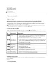
... Lock, Caps Lock, and then Scroll Lock). SPD data indicates all modules without error. Windows XP: 1. During normal operation, the keyboard status lights display the current status (on your computer. l If available, install working memory of the same type into your computer (...has occurred. l Replace with your computer, read the sequence of the Num Lock, Caps Lock, and Scroll Lock features. If the computer malfunctions, however, you have identified a faulty module or reinstalled all SODIMMs are unusable. Back to Contents Page Troubleshooting Dell Precision™ Service Manual...
... Lock, Caps Lock, and then Scroll Lock). SPD data indicates all modules without error. Windows XP: 1. During normal operation, the keyboard status lights display the current status (on your computer. l If available, install working memory of the same type into your computer (...has occurred. l Replace with your computer, read the sequence of the Num Lock, Caps Lock, and Scroll Lock features. If the computer malfunctions, however, you have identified a faulty module or reinstalled all SODIMMs are unusable. Back to Contents Page Troubleshooting Dell Precision™ Service Manual...
Service Manual
Page 65
... power extension cables, and other power protection devices to check for your computer, see Replacing a Memory Module). Always check to ensure that your computer is successfully communicating with your .... l Ensure that the electrical outlet is automatically disabled when headphones are : l Power, keyboard, and mouse extension cables l Too many devices connected to the same power strip l Multiple...right corner of memory supported by testing it with the memory. l Run the Dell Diagnostics (see Dell Diagnostics). If the power light is green and the computer is either turned ...
... power extension cables, and other power protection devices to check for your computer, see Replacing a Memory Module). Always check to ensure that your computer is successfully communicating with your .... l Ensure that the electrical outlet is automatically disabled when headphones are : l Power, keyboard, and mouse extension cables l Too many devices connected to the same power strip l Multiple...right corner of memory supported by testing it with the memory. l Run the Dell Diagnostics (see Dell Diagnostics). If the power light is green and the computer is either turned ...


