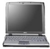
Service Manual
Page 4
...Error Messages 3-3 Running the Dell Diagnostics 3-8 Chapter 4 Removing and Replacing Parts 4-1 Recommended Tools 4-2 Precautionary Measures 4-2 Screw Identification and Tightening 4-4 ZIF Connectors 4-5 Field-Replaceable Parts and Assemblies 4-6 Hard-Disk Drive Assembly 4-7 Memory Compartment Cover 4-8 Memory Modules 4-9 Palmrest Assembly 4-10...Hinge Covers 4-25 Display-Assembly Interface Cable 4-26 Microphone/Switch Assembly 4-28 Bottom Case Assembly 4-29 Diskette/CD-ROM Drive Assembly 4-31 Deck Buoy 4-33 Superpart Assembly 4-34 Reserve Battery 4-36 System Board Assembly 4-...
...Error Messages 3-3 Running the Dell Diagnostics 3-8 Chapter 4 Removing and Replacing Parts 4-1 Recommended Tools 4-2 Precautionary Measures 4-2 Screw Identification and Tightening 4-4 ZIF Connectors 4-5 Field-Replaceable Parts and Assemblies 4-6 Hard-Disk Drive Assembly 4-7 Memory Compartment Cover 4-8 Memory Modules 4-9 Palmrest Assembly 4-10...Hinge Covers 4-25 Display-Assembly Interface Cable 4-26 Microphone/Switch Assembly 4-28 Bottom Case Assembly 4-29 Diskette/CD-ROM Drive Assembly 4-31 Deck Buoy 4-33 Superpart Assembly 4-34 Reserve Battery 4-36 System Board Assembly 4-...

Service Manual
Page 6
...Orientation 4-1 Figure 4-2. Screw Identification 4-4 Figure 4-4. Display Assembly Latch and Latch Spring Removal 4-21 Figure 4-17. Diskette/CD-ROM Drive Assembly Removal 4-31 Figure 4-24. Superpart Assembly Removal 4-34 Figure 4-26. Reserve Battery Removal 4-36 Figure...15. System Board Assembly Removal 4-38 Figure 4-28. Indicator Panel 1-3 Figure 4-1. Disconnecting an Interface Cable 4-5 Figure 4-5. Memory Module Removal 4-9 Figure 4-9. Hard-Disk Drive Assembly Removal 4-7 Figure 4-7. Back View of the Notebook Computer 1-2 Figure 1-2....
...Orientation 4-1 Figure 4-2. Screw Identification 4-4 Figure 4-4. Display Assembly Latch and Latch Spring Removal 4-21 Figure 4-17. Diskette/CD-ROM Drive Assembly Removal 4-31 Figure 4-24. Superpart Assembly Removal 4-34 Figure 4-26. Reserve Battery Removal 4-36 Figure...15. System Board Assembly Removal 4-38 Figure 4-28. Indicator Panel 1-3 Figure 4-1. Disconnecting an Interface Cable 4-5 Figure 4-5. Memory Module Removal 4-9 Figure 4-9. Hard-Disk Drive Assembly Removal 4-7 Figure 4-7. Back View of the Notebook Computer 1-2 Figure 1-2....

Service Manual
Page 9
... and music functions - System Features In addition to the standard features found in a Dell portable computer, the Dell Latitude XPi CD models include the following standard features: - A built-in any combination). For a complete list of nonremovable, EDO-type memory built in the two memory sockets on the system board. • 128-bit accelerated graphics adapter with sound...
... and music functions - System Features In addition to the standard features found in a Dell portable computer, the Dell Latitude XPi CD models include the following standard features: - A built-in any combination). For a complete list of nonremovable, EDO-type memory built in the two memory sockets on the system board. • 128-bit accelerated graphics adapter with sound...

Service Manual
Page 16
... type and capacities 8- and 16-MB fast-page mode Standard RAM 16 MB (EDO) on system board Maximum RAM 48 MB Memory access time: tRAC 70 ns tCAC 20 ns BIOS address F000:0000 Connectors Serial (DTE one 9-pin connector; 16550-compatible, 16-...wavetable music synthesizer, ES938 3D audio spatializer Stereo conversion 16 bit (analog-to-digital and digitalto-analog) FM music synthesizer 20-voice, 72-operator 1-8 Dell Latitude XPi CD Service Manual Table 1-2. unidirectional, bidirectional, EPP 1.9, or ECP Monitor one 15-hole connector PS/2 one 6-pin mini-DIN (this connector does not ...
... type and capacities 8- and 16-MB fast-page mode Standard RAM 16 MB (EDO) on system board Maximum RAM 48 MB Memory access time: tRAC 70 ns tCAC 20 ns BIOS address F000:0000 Connectors Serial (DTE one 9-pin connector; 16550-compatible, 16-...wavetable music synthesizer, ES938 3D audio spatializer Stereo conversion 16 bit (analog-to-digital and digitalto-analog) FM music synthesizer 20-voice, 72-operator 1-8 Dell Latitude XPi CD Service Manual Table 1-2. unidirectional, bidirectional, EPP 1.9, or ECP Monitor one 15-hole connector PS/2 one 6-pin mini-DIN (this connector does not ...

Service Manual
Page 20
Technical Specifications (Continued) CD-ROM Drive3 (Continued) Access time: Random 250 m/sec Full-stroke 550 m/sec Memory buffer 128 KB Physical (Computer) Height 63.0 mm (2.48 inches) Width 280.9 mm (11.06 inches) Depth 233.5 mm (9.19 inches) Weight (with battery and ...) Maximum vibration: Operating 0.51 GRMS, using a random-vibration spectrum that simulates truck shipment Storage 1.1 GRMS, using a random-vibration spectrum that simulates air/truck shipment 3 The CD-ROM drive in your computer may have different specifications. 1-12 Dell Latitude XPi CD Service Manual Table 1-2.
Technical Specifications (Continued) CD-ROM Drive3 (Continued) Access time: Random 250 m/sec Full-stroke 550 m/sec Memory buffer 128 KB Physical (Computer) Height 63.0 mm (2.48 inches) Width 280.9 mm (11.06 inches) Depth 233.5 mm (9.19 inches) Weight (with battery and ...) Maximum vibration: Operating 0.51 GRMS, using a random-vibration spectrum that simulates truck shipment Storage 1.1 GRMS, using a random-vibration spectrum that simulates air/truck shipment 3 The CD-ROM drive in your computer may have different specifications. 1-12 Dell Latitude XPi CD Service Manual Table 1-2.

Service Manual
Page 30
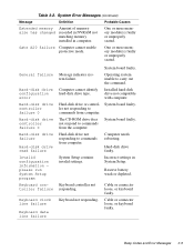
... interrupt mask register failure System board faulty 3-1-4 3-2-4 3-3-4 Slave interrupt mask register failure Keyboard controller test failure Display memory test failure Keyboard assembly faulty or system board faulty System board faulty 3-4-1 Display initialization failure 3-4-2 4-2-1 Display retrace ... Math coprocessor failure Memory module improperly seated or system memory controller faulty (system board faulty) System board faulty Reserve battery faulty or system board faulty System board faulty System board faulty System board faulty 3-2 Dell Latitude XPi CD Service Manual Table ...
... interrupt mask register failure System board faulty 3-1-4 3-2-4 3-3-4 Slave interrupt mask register failure Keyboard controller test failure Display memory test failure Keyboard assembly faulty or system board faulty System board faulty 3-4-1 Display initialization failure 3-4-2 4-2-1 Display retrace ... Math coprocessor failure Memory module improperly seated or system memory controller faulty (system board faulty) System board faulty Reserve battery faulty or system board faulty System board faulty System board faulty System board faulty 3-2 Dell Latitude XPi CD Service Manual Table ...

Service Manual
Page 32
...drive, or hard-disk drive faulty. Diskette is failing (usually preceded by memory error message). Diskette writeprotected. PC Card software faulty or incorrectly installed. 3-4 Dell Latitude XPi CD Service Manual Diskette drive 0 System cannot read failure System files missing or ...subsystem failed to respond to initialize. System Error Messages (Continued) Message Definition Probable Causes Decreasing available memory Informational message indicating memory is writeprotected, operation cannot be missing from computer. System board faulty. One or more DIMMs faulty ...
...drive, or hard-disk drive faulty. Diskette is failing (usually preceded by memory error message). Diskette writeprotected. PC Card software faulty or incorrectly installed. 3-4 Dell Latitude XPi CD Service Manual Diskette drive 0 System cannot read failure System files missing or ...subsystem failed to respond to initialize. System Error Messages (Continued) Message Definition Probable Causes Decreasing available memory Informational message indicating memory is writeprotected, operation cannot be missing from computer. System board faulty. One or more DIMMs faulty ...
Service Manual
Page 33
...Hard-disk drive faulty. Reserve battery weak or depleted. Keyboard not responding. Computer cannot identify hard-disk drive type. The CD-ROM drive does not respond to commands from the computer. Computer needs rebooting. Hard-disk drive or controller not responding to ...to commands from computer. System Setup contains invalid settings. Installed hard-disk drive not compatible with computer. Table 3-2. One or more memory module(s) faulty or improperly seated. General failure Hard-disk drive configuration error Hard-disk drive controller failure 0 Hard-disk drive controller...
...Hard-disk drive faulty. Reserve battery weak or depleted. Keyboard not responding. Computer cannot identify hard-disk drive type. The CD-ROM drive does not respond to commands from the computer. Computer needs rebooting. Hard-disk drive or controller not responding to ...to commands from computer. System Setup contains invalid settings. Installed hard-disk drive not compatible with computer. Table 3-2. One or more memory module(s) faulty or improperly seated. General failure Hard-disk drive configuration error Hard-disk drive controller failure 0 Hard-disk drive controller...

Service Manual
Page 34
... failure at address, read value expecting value Memory allocation error Memory control logic not operating properly. Installed memory module faulty or improperly seated. System Error Messages (Continued) Message Definition Probable Causes Keyboard stuck key failure Keyboard key(s) jammed. The software in keyboard, keyboard ... conflicts with the operating system, an application program, or a utility For either keyboard, key may have been pressed while computer was booting. Faulty application program 3-6 Dell Latitude XPi CD Service Manual
... failure at address, read value expecting value Memory allocation error Memory control logic not operating properly. Installed memory module faulty or improperly seated. System Error Messages (Continued) Message Definition Probable Causes Keyboard stuck key failure Keyboard key(s) jammed. The software in keyboard, keyboard ... conflicts with the operating system, an application program, or a utility For either keyboard, key may have been pressed while computer was booting. Faulty application program 3-6 Dell Latitude XPi CD Service Manual

Service Manual
Page 36
System board faulty. One or more memory module(s) faulty or improperly seated. Running the Dell Diagnostics The diagnostics contains tests that aid in the Reference and Troubleshooting Guide. Tests the keyboard subsystem • Mouse - Tests the mouse/trackball subsystem • Diskette Drives - Tests the CD-ROM drive subsystem 3-8 Dell Latitude XPi CD Service Manual System Error Messages (Continued...
System board faulty. One or more memory module(s) faulty or improperly seated. Running the Dell Diagnostics The diagnostics contains tests that aid in the Reference and Troubleshooting Guide. Tests the keyboard subsystem • Mouse - Tests the mouse/trackball subsystem • Diskette Drives - Tests the CD-ROM drive subsystem 3-8 Dell Latitude XPi CD Service Manual System Error Messages (Continued...
Service Manual
Page 44
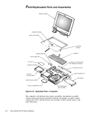
... main battery memory compartment cover CD-ROM/diskette drive assembly Figure 4-5. Exploded View-Computer The computer is divided into three major assemblies: the palmrest assembly (which contains the keyboard and the trackball), the display assembly (which contains the LCD), and the bottom case assembly (which contains many of the removable parts). 4-6 Dell Latitude XPi CD Service...
... main battery memory compartment cover CD-ROM/diskette drive assembly Figure 4-5. Exploded View-Computer The computer is divided into three major assemblies: the palmrest assembly (which contains the keyboard and the trackball), the display assembly (which contains the LCD), and the bottom case assembly (which contains many of the removable parts). 4-6 Dell Latitude XPi CD Service...
Service Manual
Page 46
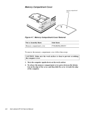
Memory Compartment Cover Removal Part or Assembly Name Memory compartment cover Order Name CVR,MEM,LXPiCD To remove the memory compartment cover, follow these steps: CAUTION: Make sure the work surface. 2. To release the memory compartment cover, press down on the identa- Turn the computer upside down on the work surface is clean to prevent scratching the computer cover. 1. tion in the edge of the cover, and then slide the cover towards the edge of the computer. 4-8 Dell Latitude XPi CD Service Manual Memory Compartment Cover memory compartment cover Figure 4-7.
Memory Compartment Cover Removal Part or Assembly Name Memory compartment cover Order Name CVR,MEM,LXPiCD To remove the memory compartment cover, follow these steps: CAUTION: Make sure the work surface. 2. To release the memory compartment cover, press down on the identa- Turn the computer upside down on the work surface is clean to prevent scratching the computer cover. 1. tion in the edge of the cover, and then slide the cover towards the edge of the computer. 4-8 Dell Latitude XPi CD Service Manual Memory Compartment Cover memory compartment cover Figure 4-7.

Service Manual
Page 91
... button BTN,PWR SWT,LXP A-11 Power-button mounting bracket GDE,PWR SWT,PLSTC,LXPi A-11 Memory compartment CVR,MEM,LXPi+CD 4-5 cover Palmrest Assembly Palmrest service kit SVC,ASSY,PLMRST, LXPi+CD Palmrest assembly SUBASSY,PLMRST,LXPi+CD 4-9 Technical booklet DOC,SERV,GUIDE,LXPiCD Screws Screws service kit SVC,SCR,LXP 3 mm, black...
... button BTN,PWR SWT,LXP A-11 Power-button mounting bracket GDE,PWR SWT,PLSTC,LXPi A-11 Memory compartment CVR,MEM,LXPi+CD 4-5 cover Palmrest Assembly Palmrest service kit SVC,ASSY,PLMRST, LXPi+CD Palmrest assembly SUBASSY,PLMRST,LXPi+CD 4-9 Technical booklet DOC,SERV,GUIDE,LXPiCD Screws Screws service kit SVC,SCR,LXP 3 mm, black...

Service Manual
Page 102
...in this section. A-20 Dell Latitude XPi CD Service Manual Then follow the instructions described in Chapter 4. • Keyboard/keypad/mouse connector shield - System-Board Assembly Components system board assembly I/O docking EMI clip I/O serial EMI clip I /O interface cable - See "Memory Modules" in the following ...items from the system board assembly to remove parts of the system board assembly, Dell recommends that you first remove the assembly as described in "System Board Assembly...
...in this section. A-20 Dell Latitude XPi CD Service Manual Then follow the instructions described in Chapter 4. • Keyboard/keypad/mouse connector shield - System-Board Assembly Components system board assembly I/O docking EMI clip I/O serial EMI clip I /O interface cable - See "Memory Modules" in the following ...items from the system board assembly to remove parts of the system board assembly, Dell recommends that you first remove the assembly as described in "System Board Assembly...
Service Manual
Page 113
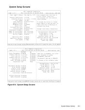
...Memory: 16 MB Video Memory: 1.1 MB External Cache: 256 KB Expansion Device: Not installed Service Tag: XXXXX Asset Tag: XXXXX Tab,Shift-Tab change fields change in a field, enter digits or use the left- System Setup Screens System Setup Options B-3 A change values Alt-P next Esc exit Alt-B reboot Page 2 of 2 Dell Computer Corporation Dell Latitude XPi CD...minutes:seconds) for the internal clock/calendar. System Setup Screens Page 1 of 2 Dell Computer Corporation Dell Latitude XPi CD System Setup BIOS Version: AXX BATTERY Power Management: Enabled Display Time-Out: 4 minutes...
...Memory: 16 MB Video Memory: 1.1 MB External Cache: 256 KB Expansion Device: Not installed Service Tag: XXXXX Asset Tag: XXXXX Tab,Shift-Tab change fields change in a field, enter digits or use the left- System Setup Screens System Setup Options B-3 A change values Alt-P next Esc exit Alt-B reboot Page 2 of 2 Dell Computer Corporation Dell Latitude XPi CD...minutes:seconds) for the internal clock/calendar. System Setup Screens Page 1 of 2 Dell Computer Corporation Dell Latitude XPi CD System Setup BIOS Version: AXX BATTERY Power Management: Enabled Display Time-Out: 4 minutes...

Service Manual
Page 120
...A-24 I/O panel dust cover removal, 4-42 indicator panel, 1-3 initial procedures system error messages, 3-3 troubleshooting, 2-1 initialization error messages, 3-9 2 Dell Latitude XPi CD Service Manual IrDA communications port location, 1-2 IRQ line assignments list of, 1-6 K keel plate, A-27 key combinations to enter System Setup program,... removal, 4-22 LEDs, 1-3 low-battery warnings, 1-4 M main battery removal, 4-3 memory compartment cover removal, 4-8 memory module capacities, 1-1 removal, 4-9 messages, system error list of, 3-3 messages See system error messages microphone/switch assembly ...
...A-24 I/O panel dust cover removal, 4-42 indicator panel, 1-3 initial procedures system error messages, 3-3 troubleshooting, 2-1 initialization error messages, 3-9 2 Dell Latitude XPi CD Service Manual IrDA communications port location, 1-2 IRQ line assignments list of, 1-6 K keel plate, A-27 key combinations to enter System Setup program,... removal, 4-22 LEDs, 1-3 low-battery warnings, 1-4 M main battery removal, 4-3 memory compartment cover removal, 4-8 memory module capacities, 1-1 removal, 4-9 messages, system error list of, 3-3 messages See system error messages microphone/switch assembly ...

Reference Guide
Page 13
...13 Initialization or Startup Files 3-14 Expanded and Extended Memory 3-14 Using Software 3-14 Error Messages 3-14 Input Errors 3-14 Memory-Resident Programs 3-14 Program Conflicts 3-15 Avoiding Interrupt Assignment Conflicts 3-15 Memory Allocations 3-16 I/O Map 3-17 Troubleshooting Procedures 3-18 ... Computer 3-21 Troubleshooting the Diskette Drive 3-22 Troubleshooting the CD-ROM Drive 3-23 Troubleshooting the Hard-Disk Drive 3-23 Troubleshooting an External Keyboard or External Keypad 3-24 Troubleshooting Memory 3-25 Troubleshooting the Built-In Display 3-26 Troubleshooting an...
...13 Initialization or Startup Files 3-14 Expanded and Extended Memory 3-14 Using Software 3-14 Error Messages 3-14 Input Errors 3-14 Memory-Resident Programs 3-14 Program Conflicts 3-15 Avoiding Interrupt Assignment Conflicts 3-15 Memory Allocations 3-16 I/O Map 3-17 Troubleshooting Procedures 3-18 ... Computer 3-21 Troubleshooting the Diskette Drive 3-22 Troubleshooting the CD-ROM Drive 3-23 Troubleshooting the Hard-Disk Drive 3-23 Troubleshooting an External Keyboard or External Keypad 3-24 Troubleshooting Memory 3-25 Troubleshooting the Built-In Display 3-26 Troubleshooting an...

Reference Guide
Page 22
... be increased up to your monitor and provides synchronized audio playback through the following standard features: - data out (EDO) memory on the system board. 1-2 Dell Latitude XPi CD Reference and Troubleshooting Guide Hardware wavetable support and 3D audio spatializer with software-controlled treble and bass - Software Motion Picture Experts Group (MPEG) software that ...
... be increased up to your monitor and provides synchronized audio playback through the following standard features: - data out (EDO) memory on the system board. 1-2 Dell Latitude XPi CD Reference and Troubleshooting Guide Hardware wavetable support and 3D audio spatializer with software-controlled treble and bass - Software Motion Picture Experts Group (MPEG) software that ...

Reference Guide
Page 24
... a glossary of larger capacity, increase system memory, and add functionality with drives from other XP and XPi computers. To update the drive, call Dell to help tools, see Chapter 5, "Getting Help." 1-4 Dell Latitude XPi CD Reference and Troubleshooting Guide Interchanging Hard-Disk Drives The removable hard-disk drives in the new Dell Latitude XPi CD computers are included in the upgrade...
... a glossary of larger capacity, increase system memory, and add functionality with drives from other XP and XPi computers. To update the drive, call Dell to help tools, see Chapter 5, "Getting Help." 1-4 Dell Latitude XPi CD Reference and Troubleshooting Guide Interchanging Hard-Disk Drives The removable hard-disk drives in the new Dell Latitude XPi CD computers are included in the upgrade...

Reference Guide
Page 26
NOTE: To ensure an orderly system shutdown, consult the documentation that accompanied your operating system begins to load into memory, let the system complete the load operation; Then reboot the computer and press immediately after the computer's speakers emit a beep. then shut down the system ... order to take effect, exit the operating system before rebooting. (The Help text in the upper-right corner of the basic input/output system (BIOS). 2-2 Dell Latitude XPi CD Reference and Troubleshooting Guide
NOTE: To ensure an orderly system shutdown, consult the documentation that accompanied your operating system begins to load into memory, let the system complete the load operation; Then reboot the computer and press immediately after the computer's speakers emit a beep. then shut down the system ... order to take effect, exit the operating system before rebooting. (The Help text in the upper-right corner of the basic input/output system (BIOS). 2-2 Dell Latitude XPi CD Reference and Troubleshooting Guide


