Service Manual
Page 9
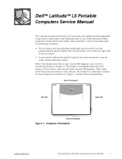
... open nearly 180 degrees, use a book or something similar to the bottom case should never exceed 180 degrees. Computer Orientation support.dell.com Dell Latitude LS Portable Computers Service Manual 1 Dell™ Latitude™ LS Portable Computers Service Manual This manual provides instructions for removing and replacing field-replaceable components, assemblies, and subassemblies in Figure 1 unless otherwise specified. back of computer left...
... open nearly 180 degrees, use a book or something similar to the bottom case should never exceed 180 degrees. Computer Orientation support.dell.com Dell Latitude LS Portable Computers Service Manual 1 Dell™ Latitude™ LS Portable Computers Service Manual This manual provides instructions for removing and replacing field-replaceable components, assemblies, and subassemblies in Figure 1 unless otherwise specified. back of computer left...
Service Manual
Page 10
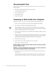
...reduce the potential for 4 seconds. 3. Turn the computer over and remove the main battery assembly from the computer. 7. If you service the computer. 8. NOTICE: Make sure that the computer is turned off the computer and any installed PC Cards. Turn off and not in... Port Replicator (APR), undock the computer. 4. Recommended Tools Most of the procedures in this manual require the use of one or more of the battery bay (see Figure 2). 2 Dell Latitude LS Portable Computers Service Manual Remove the power cable. 6. Save any work surface is docked in suspend-todisk mode (S2D)....
...reduce the potential for 4 seconds. 3. Turn the computer over and remove the main battery assembly from the computer. 7. If you service the computer. 8. NOTICE: Make sure that the computer is turned off the computer and any installed PC Cards. Turn off and not in... Port Replicator (APR), undock the computer. 4. Recommended Tools Most of the procedures in this manual require the use of one or more of the battery bay (see Figure 2). 2 Dell Latitude LS Portable Computers Service Manual Remove the power cable. 6. Save any work surface is docked in suspend-todisk mode (S2D)....

Service Manual
Page 11
... the correct length. Make sure that might harm components. Otherwise, you work, periodically touch the I /O connector on the back of the computer. Figure 3. support.dell.com Dell Latitude LS Portable Computers Service Manual 3 Screw Identification NOTICE: When reinstalling a screw, you must use a screw of the correct screws for correct length. Main Battery Assembly Removal 9. Figure 3 shows...
... the correct length. Make sure that might harm components. Otherwise, you work, periodically touch the I /O connector on the back of the computer. Figure 3. support.dell.com Dell Latitude LS Portable Computers Service Manual 3 Screw Identification NOTICE: When reinstalling a screw, you must use a screw of the correct screws for correct length. Main Battery Assembly Removal 9. Figure 3 shows...
Service Manual
Page 12
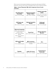
...) IDE Connector: IDE connector screws (2 each) Fan: M2 x 3.5 mm (2 each) Speaker: M2 x 3.5 mm (2 each) Audio I/O Cover: M2 x 4 mm (2 each) System Board Assembly: M2 x 3.5 mm (6 each) 4 Dell Latitude LS Portable Computers Service Manual
...) IDE Connector: IDE connector screws (2 each) Fan: M2 x 3.5 mm (2 each) Speaker: M2 x 3.5 mm (2 each) Audio I/O Cover: M2 x 4 mm (2 each) System Board Assembly: M2 x 3.5 mm (6 each) 4 Dell Latitude LS Portable Computers Service Manual
Service Manual
Page 13
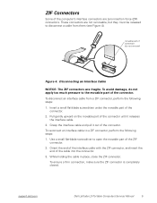
... the interface cable and pull it releases the interface cable. 3. Use a small flat-blade screwdriver to a ZIF connector, perform the following steps: 1. support.dell.com Dell Latitude LS Portable Computers Service Manual 5 To reconnect an interface cable to open the movable part of the connector. Orient the end of the interface cable with the ZIF connector...
... the interface cable and pull it releases the interface cable. 3. Use a small flat-blade screwdriver to a ZIF connector, perform the following steps: 1. support.dell.com Dell Latitude LS Portable Computers Service Manual 5 To reconnect an interface cable to open the movable part of the connector. Orient the end of the interface cable with the ZIF connector...
Service Manual
Page 14
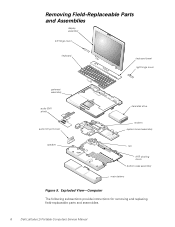
Removing Field-Replaceable Parts and Assemblies display assembly left hinge cover keyboard keyboard bezel right hinge cover palmrest assembly audio EMI shield audio I/O port cover hard-disk drive modem system board assembly speaker fan APR docking doors bottom case assembly main battery Figure 5. Exploded View-Computer The following subsections provide instructions for removing and replacing field-replaceable parts and assemblies. 6 Dell Latitude LS Portable Computers Service Manual
Removing Field-Replaceable Parts and Assemblies display assembly left hinge cover keyboard keyboard bezel right hinge cover palmrest assembly audio EMI shield audio I/O port cover hard-disk drive modem system board assembly speaker fan APR docking doors bottom case assembly main battery Figure 5. Exploded View-Computer The following subsections provide instructions for removing and replacing field-replaceable parts and assemblies. 6 Dell Latitude LS Portable Computers Service Manual
Service Manual
Page 15
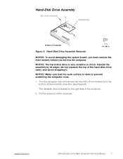
... Figure 6. Pull the drive out of the hard-disk drive case), and avoid dropping it. The hard-disk drive is clean to shock. support.dell.com Dell Latitude LS Portable Computers Service Manual 7 NOTICE: The hard-disk drive is very sensitive to prevent scratching the computer cover. 1. Hard-Disk Drive Assembly Removal NOTICE: To avoid damaging...
... Figure 6. Pull the drive out of the hard-disk drive case), and avoid dropping it. The hard-disk drive is clean to shock. support.dell.com Dell Latitude LS Portable Computers Service Manual 7 NOTICE: The hard-disk drive is very sensitive to prevent scratching the computer cover. 1. Hard-Disk Drive Assembly Removal NOTICE: To avoid damaging...

Service Manual
Page 16
Keyboard Bezel Removal NOTICE: To avoid damaging the system board, you must remove the main battery before you service the computer. Lift the keyboard bezel. 8 Dell Latitude LS Portable Computers Service Manual NOTICE: To avoid damaging the microphone, do not put any objects into the microphone hole (see Figure 7). 2. Place the point of a paper clip, a very small...
Keyboard Bezel Removal NOTICE: To avoid damaging the system board, you must remove the main battery before you service the computer. Lift the keyboard bezel. 8 Dell Latitude LS Portable Computers Service Manual NOTICE: To avoid damaging the microphone, do not put any objects into the microphone hole (see Figure 7). 2. Place the point of a paper clip, a very small...
Service Manual
Page 17
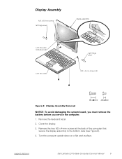
... back of the computer that secure the display assembly to the bottom case (see Figure 8). 4. Remove the keyboard bezel. 2. Close the display. 3. support.dell.com Dell Latitude LS Portable Computers Service Manual 9 Turn the computer upside down clip LCD flex cable right hinge cover M2 x 4-mm screws (4) Figure 8. Display Assembly Removal NOTICE: To avoid damaging the...
... back of the computer that secure the display assembly to the bottom case (see Figure 8). 4. Remove the keyboard bezel. 2. Close the display. 3. support.dell.com Dell Latitude LS Portable Computers Service Manual 9 Turn the computer upside down clip LCD flex cable right hinge cover M2 x 4-mm screws (4) Figure 8. Display Assembly Removal NOTICE: To avoid damaging the...

Service Manual
Page 18
... over the left hinge cover and an R is stamped on the bottom of the computer that secure the display assembly to close completely. 10 Dell Latitude LS Portable Computers Service Manual To replace the display assembly, perform the following steps: 1. Insert the left and right hinge posts into the holes at the left and right...
... over the left hinge cover and an R is stamped on the bottom of the computer that secure the display assembly to close completely. 10 Dell Latitude LS Portable Computers Service Manual To replace the display assembly, perform the following steps: 1. Insert the left and right hinge posts into the holes at the left and right...

Service Manual
Page 19
... step 6. 9. Reinstall the two M2 x 4-mm screws in the back of the computer that secure the display assembly to the bottom case. support.dell.com Dell Latitude LS Portable Computers Service Manual 11 Tighten the two screws that secure the display assembly to the back of the right hinge cover. An L is stamped on the bottom...
... step 6. 9. Reinstall the two M2 x 4-mm screws in the back of the computer that secure the display assembly to the bottom case. support.dell.com Dell Latitude LS Portable Computers Service Manual 11 Tighten the two screws that secure the display assembly to the back of the right hinge cover. An L is stamped on the bottom...
Service Manual
Page 20
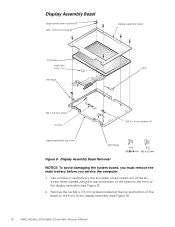
... out of the six screw holes located along the top and bottom of the bezel on the front of the display assembly (see Figure 9). 12 Dell Latitude LS Portable Computers Service Manual Display Assembly Bezel Removal NOTICE: To avoid damaging the system board, you must remove the main battery before you... service the computer. 1. Remove the six M2 x 3.5-mm screws located at the top and bottom of the bezel on the front of the display assembly (see ...
... out of the six screw holes located along the top and bottom of the bezel on the front of the display assembly (see Figure 9). 12 Dell Latitude LS Portable Computers Service Manual Display Assembly Bezel Removal NOTICE: To avoid damaging the system board, you must remove the main battery before you... service the computer. 1. Remove the six M2 x 3.5-mm screws located at the top and bottom of the bezel on the front of the display assembly (see ...
Service Manual
Page 21
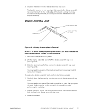
...10). Holding the latch, stretch the spring slightly and set the display-assembly latch in place in the display assembly top cover. 3. support.dell.com Dell Latitude LS Portable Computers Service Manual 13 Separate the bezel from the display assembly. You may need to use a small flat-blade screwdriver to place the spring over the post... top cover post Figure 10. Display Assembly Latch Removal NOTICE: To avoid damaging the system board, you must remove the main battery before you service the computer. 1. Carefully place the latch spring over the post. Reinstall the bezel.
...10). Holding the latch, stretch the spring slightly and set the display-assembly latch in place in the display assembly top cover. 3. support.dell.com Dell Latitude LS Portable Computers Service Manual 13 Separate the bezel from the display assembly. You may need to use a small flat-blade screwdriver to place the spring over the post... top cover post Figure 10. Display Assembly Latch Removal NOTICE: To avoid damaging the system board, you must remove the main battery before you service the computer. 1. Carefully place the latch spring over the post. Reinstall the bezel.

Service Manual
Page 22
... the four M2 x 3.5-mm screws on the back of the display assembly that secures the inverter to the top cover (see Figure 11). 14 Dell Latitude LS Portable Computers Service Manual Ground yourself by touching the unpainted metal surface of the I/O panel on the left and right sides of the computer. 2. LCD Panel LCD panel...
... the four M2 x 3.5-mm screws on the back of the display assembly that secures the inverter to the top cover (see Figure 11). 14 Dell Latitude LS Portable Computers Service Manual Ground yourself by touching the unpainted metal surface of the I/O panel on the left and right sides of the computer. 2. LCD Panel LCD panel...

Service Manual
Page 23
... the LCD panel, insert the right edge of the LCD panel into the right end of the inverter (see Figure 11). 10. d. support.dell.com Dell Latitude LS Portable Computers Service Manual 15 8. Disconnect the narrow flex cable from the top cover. 13. Lift the LCD panel out of the LCD panel. Connect the LCD flex...
... the LCD panel, insert the right edge of the LCD panel into the right end of the inverter (see Figure 11). 10. d. support.dell.com Dell Latitude LS Portable Computers Service Manual 15 8. Disconnect the narrow flex cable from the top cover. 13. Lift the LCD panel out of the LCD panel. Connect the LCD flex...

Service Manual
Page 24
... to the top cover. 11. Remove the two M2.6 x 4-mm screws that secure the LCD panel to the connector on the right hinge. 16 Dell Latitude LS Portable Computers Service Manual When the plug is stamped on the right side of the plug should not be visible. Reinstall the four M2 x 3.5-mm screws, in the...
... to the top cover. 11. Remove the two M2.6 x 4-mm screws that secure the LCD panel to the connector on the right hinge. 16 Dell Latitude LS Portable Computers Service Manual When the plug is stamped on the right side of the plug should not be visible. Reinstall the four M2 x 3.5-mm screws, in the...

Service Manual
Page 25
... of the keyboard assembly (see Figure 9). NOTICE: To avoid damaging the system board, you must remove the main battery before you service the computer. Remove the four M2 x 4-mm screws located across the top of the keyboard in the palmrest assembly. 3. Release ... it is clean to the computer. 5. Keyboard Assembly M2 x 4-mm screws (4) keyboard assembly keyboard cable Figure 12. support.dell.com Dell Latitude LS Portable Computers Service Manual 17 Keyboard Assembly Removal To remove the keyboard assembly, perform the following steps. NOTICE: Make sure that the work surface is...
... of the keyboard assembly (see Figure 9). NOTICE: To avoid damaging the system board, you must remove the main battery before you service the computer. Remove the four M2 x 4-mm screws located across the top of the keyboard in the palmrest assembly. 3. Release ... it is clean to the computer. 5. Keyboard Assembly M2 x 4-mm screws (4) keyboard assembly keyboard cable Figure 12. support.dell.com Dell Latitude LS Portable Computers Service Manual 17 Keyboard Assembly Removal To remove the keyboard assembly, perform the following steps. NOTICE: Make sure that the work surface is...

Service Manual
Page 26
... assembly. To help align the tabs with the left and right surfaces of the keyboard in the palmrest assembly. Reinstall the keyboard bezel. 18 Dell Latitude LS Portable Computers Service Manual NOTICE: Position the keyboard cable so it is not twisted when it is seated in the palmrest assembly. Verify that the keyboard is important...
... assembly. To help align the tabs with the left and right surfaces of the keyboard in the palmrest assembly. Reinstall the keyboard bezel. 18 Dell Latitude LS Portable Computers Service Manual NOTICE: Position the keyboard cable so it is not twisted when it is seated in the palmrest assembly. Verify that the keyboard is important...

Service Manual
Page 27
...slot on the computer's back panel. 4. Memory Module Removal NOTICE: To avoid damaging the system board, you must remove the main battery before you service the computer. 1. Align the memory module's edge connector with the slot in only one way. 2. The memory module is notched so that the ... fit into the memory module socket. 3. Pivot the memory module down until it should pop up slightly) (see Figure 13). 5. support.dell.com Dell Latitude LS Portable Computers Service Manual 19 Remove the keyboard assembly. 3. Memory Module memory module inner tabs (2) Figure 13.
...slot on the computer's back panel. 4. Memory Module Removal NOTICE: To avoid damaging the system board, you must remove the main battery before you service the computer. 1. Align the memory module's edge connector with the slot in only one way. 2. The memory module is notched so that the ... fit into the memory module socket. 3. Pivot the memory module down until it should pop up slightly) (see Figure 13). 5. support.dell.com Dell Latitude LS Portable Computers Service Manual 19 Remove the keyboard assembly. 3. Memory Module memory module inner tabs (2) Figure 13.

Service Manual
Page 28
Remove the six M2.6 x 1.6-mm screws located in the battery bay (see Figure 15). 20 Dell Latitude LS Portable Computers Service Manual Turn the computer right-side up. 7. Remove the four black M2 x 4-mm screws across the top of the computer (see Figure 14). Remove the keyboard ... as each end of the palmrest, status lights, and touch pad assembly. Remove the display assembly. 3. NOTICE: Make sure that the work surface. 5. If you service the computer. 1. Palmrest Assembly M2.6 x 1.6-mm screws (6) Figure 14.
Remove the six M2.6 x 1.6-mm screws located in the battery bay (see Figure 15). 20 Dell Latitude LS Portable Computers Service Manual Turn the computer right-side up. 7. Remove the four black M2 x 4-mm screws across the top of the computer (see Figure 14). Remove the keyboard ... as each end of the palmrest, status lights, and touch pad assembly. Remove the display assembly. 3. NOTICE: Make sure that the work surface. 5. If you service the computer. 1. Palmrest Assembly M2.6 x 1.6-mm screws (6) Figure 14.


