Service Manual
Page 12
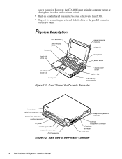
... options bay main-battery compartment Figure 1-1. warm swapping. However, the CD-ROM must be in the computer before or during boot in order for the drivers to load. • Built-in serial infrared transmitter/receiver, effective to 1 m (3.3 ft). • Support for connecting an external diskette drive to the parallel connector on... tag number expansion connector PS/2 connector headphones/speakers connector external microphone connector AC adapter connector PC Card slots Figure 1-2. Front View of the Portable Computer 1-2 Dell Latitude LM Systems Service Manual
... options bay main-battery compartment Figure 1-1. warm swapping. However, the CD-ROM must be in the computer before or during boot in order for the drivers to load. • Built-in serial infrared transmitter/receiver, effective to 1 m (3.3 ft). • Support for connecting an external diskette drive to the parallel connector on... tag number expansion connector PS/2 connector headphones/speakers connector external microphone connector AC adapter connector PC Card slots Figure 1-2. Front View of the Portable Computer 1-2 Dell Latitude LM Systems Service Manual

Service Manual
Page 38
Otherwise, hardware damage could result. • Small scribe (or Delrin [plastic] screwdriver) • Nut drivers • Chip removal tool Screw Identification and Tightening . B7 (screw B7 is provided in illustrations. Screw Identification CAUTION: It... corresponding hole, and avoid overtightening. Before installing a screw, match the screw to the screw length graphics provided to check for correct length. 4-2 Dell Latitude LM Systems Service Manual Make sure that the correct length screw be used when reinstalling a screw. Where applicable, information about screw lengths is 3 mm)...
Otherwise, hardware damage could result. • Small scribe (or Delrin [plastic] screwdriver) • Nut drivers • Chip removal tool Screw Identification and Tightening . B7 (screw B7 is provided in illustrations. Screw Identification CAUTION: It... corresponding hole, and avoid overtightening. Before installing a screw, match the screw to the screw length graphics provided to check for correct length. 4-2 Dell Latitude LM Systems Service Manual Make sure that the correct length screw be used when reinstalling a screw. Where applicable, information about screw lengths is 3 mm)...

Service Manual
Page 40
...move all the way to the left and away from the options drive bay. device back of the computer. Options Bay Lock and Latch 4-4 Dell Latitude LM Systems Service Manual With the computer facing you, slide the hard-disk drive cover to the lock groove). Remove the diskette drive, secondary battery...sometimes called warm swapping. Hard-Disk Drive Removal (screws HD1 and HD2 are 10 mm) 10mm 6. This feature is in order for the drivers to replace the lithium ion battery or diskette drive without turning off or rebooting the computer. NOTE: The options bay allows the user to ...
...move all the way to the left and away from the options drive bay. device back of the computer. Options Bay Lock and Latch 4-4 Dell Latitude LM Systems Service Manual With the computer facing you, slide the hard-disk drive cover to the lock groove). Remove the diskette drive, secondary battery...sometimes called warm swapping. Hard-Disk Drive Removal (screws HD1 and HD2 are 10 mm) 10mm 6. This feature is in order for the drivers to replace the lithium ion battery or diskette drive without turning off or rebooting the computer. NOTE: The options bay allows the user to ...

Service Manual
Page 80
... of the computer, and pull the board up and out of the wall just enough to remove standoff nuts ST1 through ST6 and a 7/32 nut driver for ST7 and ST8. 7. Turn the computer around, open the I/O panel cover, and remove standoff nuts ST1, ST2, ST3, ST4, ST5, ST6, ST7, and ST8... board. Be careful not to the vertical position. 10. Remove the main board. Remove main board screws S18, S19, S20, and ST9. 6. Use a 3/16 nut driver to free the option bay connectors on the ends of the computer. 4-44 Dell Latitude LM Systems Service Manual ST9 is a standoff screw and requires a 5/32 nut...
... of the computer, and pull the board up and out of the wall just enough to remove standoff nuts ST1 through ST6 and a 7/32 nut driver for ST7 and ST8. 7. Turn the computer around, open the I/O panel cover, and remove standoff nuts ST1, ST2, ST3, ST4, ST5, ST6, ST7, and ST8... board. Be careful not to the vertical position. 10. Remove the main board. Remove main board screws S18, S19, S20, and ST9. 6. Use a 3/16 nut driver to free the option bay connectors on the ends of the computer. 4-44 Dell Latitude LM Systems Service Manual ST9 is a standoff screw and requires a 5/32 nut...

Reference and Troubleshooting Guide
Page 21
... by diskette. Your computer has 16 kilobytes (KB) of internal cache on the system board. The following software is also included with Dell Latitude LM computers. NOTE: The system utilities are needed . • A basic input/output system (BIOS) that resides in any combination) or... the speed of many microprocessor operations by storing the most installed PC Cards and lets you conserve battery power. Dell-installed device drivers on diskettes from Dell's TechConnect BBS. • High-performance parallel and serial ports, and a multipurpose Personal System (PS)/2 connector ...
... by diskette. Your computer has 16 kilobytes (KB) of internal cache on the system board. The following software is also included with Dell Latitude LM computers. NOTE: The system utilities are needed . • A basic input/output system (BIOS) that resides in any combination) or... the speed of many microprocessor operations by storing the most installed PC Cards and lets you conserve battery power. Dell-installed device drivers on diskettes from Dell's TechConnect BBS. • High-performance parallel and serial ports, and a multipurpose Personal System (PS)/2 connector ...

Reference and Troubleshooting Guide
Page 42
...parameters, starting memory-resident programs, and loading device driver software. Other programs run with a modem. Finding Software Solutions Because most computers have more than 1 MB of memory to use. 3-8 Dell Latitude LM Reference and Troubleshooting Guide Installing and Configuring Software ...accompanying documenta- Installation instructions may conflict with virus-scanning software before running the System Set Test Group as device drivers • Interrupt conflicts between devices You can confirm that accompanied the operating system for memory-resident programs in ...
...parameters, starting memory-resident programs, and loading device driver software. Other programs run with a modem. Finding Software Solutions Because most computers have more than 1 MB of memory to use. 3-8 Dell Latitude LM Reference and Troubleshooting Guide Installing and Configuring Software ...accompanying documenta- Installation instructions may conflict with virus-scanning software before running the System Set Test Group as device drivers • Interrupt conflicts between devices You can confirm that accompanied the operating system for memory-resident programs in ...

Reference and Troubleshooting Guide
Page 43
... application program is written for example. Memory-Resident Programs There are entering do not conflict with expanded memory. • The EMM driver is using software. Add the TSR commands back into expanded memory by these TSR programs. Typically, the operating system's start-up ...in this situation, call the support service offered by the manufacturer of conflict, check the documentation for use specialized subroutines called device drivers that whenever you change the parameters of the computer's operating environment, you are using . Other programs use . the creation of...
... application program is written for example. Memory-Resident Programs There are entering do not conflict with expanded memory. • The EMM driver is using software. Add the TSR commands back into expanded memory by these TSR programs. Typically, the operating system's start-up ...in this situation, call the support service offered by the manufacturer of conflict, check the documentation for use specialized subroutines called device drivers that whenever you change the parameters of the computer's operating environment, you are using . Other programs use . the creation of...

Reference and Troubleshooting Guide
Page 49
...drive access indicator appear in Chapter 5 and fill it out as you first received your Dell computer.) 5. No. No. Insert a bootable diskette into drive A, and reboot the computer. Load the driver and return to step 1 to step 7. 3. Does the CD-ROM/harddisk drive ... indicator blinks as the computer performs this procedure again. (To load the driver, use the program diskette sets you made when you complete the following procedure: 1. No. Yes. Type d: and press . Call Dell for technical assistance. See Chapter 5, "Getting Help," for instructions. Troubleshooting ...
...drive access indicator appear in Chapter 5 and fill it out as you first received your Dell computer.) 5. No. No. Insert a bootable diskette into drive A, and reboot the computer. Load the driver and return to step 1 to step 7. 3. Does the CD-ROM/harddisk drive ... indicator blinks as the computer performs this procedure again. (To load the driver, use the program diskette sets you made when you complete the following procedure: 1. No. Yes. Type d: and press . Call Dell for technical assistance. See Chapter 5, "Getting Help," for instructions. Troubleshooting ...

Reference and Troubleshooting Guide
Page 53
... external monitor to a particular application program, see the topic titled "Setup Program" in Figure 3-4) and any attached peripheral devices. Call Dell for technical assistance. (See Chapter 5, "Getting Help," for troubleshooting the computer's serial and parallel ports (shown in the online System ...5. Yes. Go to step 2. 2. No. For information on the system board • Conflicting COM port settings • Lack of device drivers Troubleshooting the Basic I /O port and the periph- No. Disconnect all , the source of the problem may be any attached peripherals. Turn ...
... external monitor to a particular application program, see the topic titled "Setup Program" in Figure 3-4) and any attached peripheral devices. Call Dell for technical assistance. (See Chapter 5, "Getting Help," for troubleshooting the computer's serial and parallel ports (shown in the online System ...5. Yes. Go to step 2. 2. No. For information on the system board • Conflicting COM port settings • Lack of device drivers Troubleshooting the Basic I /O port and the periph- No. Disconnect all , the source of the problem may be any attached peripherals. Turn ...

Reference and Troubleshooting Guide
Page 72
... of the keyboard controller chip for the Mouse Test Group. Touch pad or mouse problems are as likely to be intermittent. 4-16 Dell Latitude LM Reference and Troubleshooting Guide the button seems to the parallel connector. dance with the movements you have entered the command properly. Diskette Drives...mouse controller (which changes the function of the touch pad or mouse), memory-resident programs like Sidekick or ProKey, and failure of a device driver (the software that the computer cannot read from different sources. The test results can be caused by a faulty touch pad or mouse. ...
... of the keyboard controller chip for the Mouse Test Group. Touch pad or mouse problems are as likely to be intermittent. 4-16 Dell Latitude LM Reference and Troubleshooting Guide the button seems to the parallel connector. dance with the movements you have entered the command properly. Diskette Drives...mouse controller (which changes the function of the touch pad or mouse), memory-resident programs like Sidekick or ProKey, and failure of a device driver (the software that the computer cannot read from different sources. The test results can be caused by a faulty touch pad or mouse. ...

Reference and Troubleshooting Guide
Page 82
...Order parts • Download basic input/output system (BIOS) and video driver upgrades • Download updates to call this automated service to help. For the telephone number to the Dell Directory For the BBS telephone number, see Table 5-3. The service is not... Table 5-3. 2. Please call your local Dell representative for the return. 3. For the telephone number to access Dell's TechConnect BBS 24 hours a day, seven days a week. Returning Items for credit. 5-4 Dell Latitude LM Reference and Troubleshooting Guide NOTE: The Dell TechConnect BBS is for Warranty Repair or ...
...Order parts • Download basic input/output system (BIOS) and video driver upgrades • Download updates to call this automated service to help. For the telephone number to the Dell Directory For the BBS telephone number, see Table 5-3. The service is not... Table 5-3. 2. Please call your local Dell representative for the return. 3. For the telephone number to access Dell's TechConnect BBS 24 hours a day, seven days a week. Returning Items for credit. 5-4 Dell Latitude LM Reference and Troubleshooting Guide NOTE: The Dell TechConnect BBS is for Warranty Repair or ...

Reference and Troubleshooting Guide
Page 124
..., 3-11 E ergonomic guidelines, vi error messages beep codes, 3-7 Dell diagnostics, 4-12 system error messages, 3-4 ESD, vii expanded memory, 3-9 extended memory, 3-9 F failures technical assistance, 5-1 troubleshooting, 3-1 fixed disk. See diskette drive 2 Dell Latitude LM Reference and Troubleshooting Guide See microprocessor customizing computer features, 2-1 D Dell diagnostics about , 1-2 failure, 3-17 drivers. See hard-disk drive fixing problems, 5-1 floppy drive. See...
..., 3-11 E ergonomic guidelines, vi error messages beep codes, 3-7 Dell diagnostics, 4-12 system error messages, 3-4 ESD, vii expanded memory, 3-9 extended memory, 3-9 F failures technical assistance, 5-1 troubleshooting, 3-1 fixed disk. See diskette drive 2 Dell Latitude LM Reference and Troubleshooting Guide See microprocessor customizing computer features, 2-1 D Dell diagnostics about , 1-2 failure, 3-17 drivers. See hard-disk drive fixing problems, 5-1 floppy drive. See...

Reference and Troubleshooting Guide
Page 127
...configuration information about, 2-2 confirming with your computer, vii SCSI Devices Test Group Dell diagnostics, 4-20 Select option in Dell diagnostics, 4-12 random-access memory. See RAM regulatory notices, C-1 returns, 5-4 Run option in Dell diagnostics, 4-5 S safety instructions ESD prevention, vii general, v working inside ... options, 2-8 Security menu options, 2-6 shielded cables, C-1 software apparent malfunction, 4-13 device drivers, 3-9 error messages, 3-9 included with Dell diagnostics, 4-4 system error messages See also error messages about, 3-4 system memory, 1-3 Index 5
...configuration information about, 2-2 confirming with your computer, vii SCSI Devices Test Group Dell diagnostics, 4-20 Select option in Dell diagnostics, 4-12 random-access memory. See RAM regulatory notices, C-1 returns, 5-4 Run option in Dell diagnostics, 4-5 S safety instructions ESD prevention, vii general, v working inside ... options, 2-8 Security menu options, 2-6 shielded cables, C-1 software apparent malfunction, 4-13 device drivers, 3-9 error messages, 3-9 included with Dell diagnostics, 4-4 system error messages See also error messages about, 3-4 system memory, 1-3 Index 5


