Service Manual
Page 12
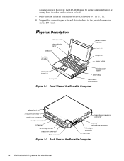
... connecting an external diskette drive to the parallel connector on the I /O panel service tag number expansion connector PS/2 connector headphones/speakers connector external microphone connector AC adapter connector PC Card slots Figure 1-2. Front View of the Portable Computer 1-2 Dell Latitude LM Systems Service Manual warm swapping. Back View of the Portable Computer infrared port serial port...
... connecting an external diskette drive to the parallel connector on the I /O panel service tag number expansion connector PS/2 connector headphones/speakers connector external microphone connector AC adapter connector PC Card slots Figure 1-2. Front View of the Portable Computer 1-2 Dell Latitude LM Systems Service Manual warm swapping. Back View of the Portable Computer infrared port serial port...
Service Manual
Page 14
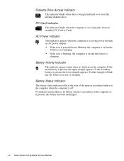
... battery in the computer when the computer is no battery (main or secondary) in the computer or, if present, the battery has been discharged. 1-4 Dell Latitude LM Systems Service Manual No indicator means there is off. If the main battery is in the computer. Battery Activity Indicator This indicator appears when there are batteries in...
... battery in the computer when the computer is no battery (main or secondary) in the computer or, if present, the battery has been discharged. 1-4 Dell Latitude LM Systems Service Manual No indicator means there is off. If the main battery is in the computer. Battery Activity Indicator This indicator appears when there are batteries in...
Service Manual
Page 16
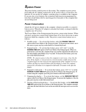
... the Setup program has power conservation features. To resume using the computer, press the power button on the next time the microprocessor accesses the drive. 1-6 Dell Latitude LM Systems Service Manual System Power The power button controls power to two batteries.
... the Setup program has power conservation features. To resume using the computer, press the power button on the next time the microprocessor accesses the drive. 1-6 Dell Latitude LM Systems Service Manual System Power The power button controls power to two batteries.

Service Manual
Page 18
Technical Specifications Table 1-2. must be installed in matched pairs Standard RAM 8 MB on system board Maximum RAM 40 MB 1-8 Dell Latitude LM Systems Service Manual and 5-V PC Card connector size . . . . . 68 pins Data width (maximum) . . . . . 32 bits Memory Architecture fast-page mode, two-way interleaved Memory module capacities . . 4, 8, and 16 ...
Technical Specifications Table 1-2. must be installed in matched pairs Standard RAM 8 MB on system board Maximum RAM 40 MB 1-8 Dell Latitude LM Systems Service Manual and 5-V PC Card connector size . . . . . 68 pins Data width (maximum) . . . . . 32 bits Memory Architecture fast-page mode, two-way interleaved Memory module capacities . . 4, 8, and 16 ...

Service Manual
Page 20
...) Maximum resolution 800 x 600 pixels; 256 colors Refresh rate (typical 70 Hz Response time (typical) . . . . . 300 ms Operating angle 0° (closed) to 135° 1-10 Dell Latitude LM Systems Service Manual Table 1-2.
...) Maximum resolution 800 x 600 pixels; 256 colors Refresh rate (typical 70 Hz Response time (typical) . . . . . 300 ms Operating angle 0° (closed) to 135° 1-10 Dell Latitude LM Systems Service Manual Table 1-2.

Service Manual
Page 22
... features such as charge time, operating time, and life span can vary according to the conditions under which the computer and battery are used. 1-12 Dell Latitude LM Systems Service Manual
... features such as charge time, operating time, and life span can vary according to the conditions under which the computer and battery are used. 1-12 Dell Latitude LM Systems Service Manual

Service Manual
Page 24
... 2438 m (0 ft to 8,000 ft) Storage 0 m to 12,192 m (0 ft to 40,000 ft) 2 Measured with the hard-disk drive in head-parked position. 1-14 Dell Latitude LM Systems Service Manual
... 2438 m (0 ft to 8,000 ft) Storage 0 m to 12,192 m (0 ft to 40,000 ft) 2 Measured with the hard-disk drive in head-parked position. 1-14 Dell Latitude LM Systems Service Manual

Service Manual
Page 26
... files and exited all open application programs if possible. If the display is operating from the main board, verify that its associated buttons operate freely. 2-2 Dell Latitude LM Systems Service Manual b. If the computer is on . Remove any installed PC Cards from an AC adapter, verify the following procedure, see if there is free of...
... files and exited all open application programs if possible. If the display is operating from the main board, verify that its associated buttons operate freely. 2-2 Dell Latitude LM Systems Service Manual b. If the computer is on . Remove any installed PC Cards from an AC adapter, verify the following procedure, see if there is free of...

Service Manual
Page 28
... to data being transferred to or from the drives. See "Running the Dell Diagnostics" in Chapter 3. Proceed to the next section, "Eliminating Resource Conflicts." 2-4 Dell Latitude LM Systems Service Manual No. Depending on . Does the Diagnostics Menu appear on the display? Insert... another copy of the keyboard. See "Running the Dell Diagnostics" in Chapter 3. Watch the indicators at the...
... to data being transferred to or from the drives. See "Running the Dell Diagnostics" in Chapter 3. Proceed to the next section, "Eliminating Resource Conflicts." 2-4 Dell Latitude LM Systems Service Manual No. Depending on . Does the Diagnostics Menu appear on the display? Insert... another copy of the keyboard. See "Running the Dell Diagnostics" in Chapter 3. Watch the indicators at the...

Service Manual
Page 32
... of low byte on memory faulty main board bus Check ROM copyright notice failure Faulty main board Interrupt mask register failure Faulty main board 3-2 Dell Latitude LM Systems Service Manual POST Beep Codes Error Probable Causes Memory module not being properly identified or used Faulty memory module or faulty main board ROM BIOS checksum failure...
... of low byte on memory faulty main board bus Check ROM copyright notice failure Faulty main board Interrupt mask register failure Faulty main board 3-2 Dell Latitude LM Systems Service Manual POST Beep Codes Error Probable Causes Memory module not being properly identified or used Faulty memory module or faulty main board ROM BIOS checksum failure...
Service Manual
Page 34
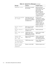
... on diskette in I/O bus Faulty main board. Faulty main board. Shadow RAM failed at offset: nnnn Shadow RAM failed at address nnnn. Faulty microprocessor. 3-4 Dell Latitude LM Systems Service Manual System battery is dead-Replace and run Setup CMOS battery dead. bus at address nnnn. Faulty supports data stored in system Faulty main board. NVRAM...
... on diskette in I/O bus Faulty main board. Faulty main board. Shadow RAM failed at offset: nnnn Shadow RAM failed at address nnnn. Faulty microprocessor. 3-4 Dell Latitude LM Systems Service Manual System battery is dead-Replace and run Setup CMOS battery dead. bus at address nnnn. Faulty supports data stored in system Faulty main board. NVRAM...

Service Manual
Page 36
... use a backup copy of the main board • Video - Tests a SCSI hard-disk drive subsystem NOTE: This test does not apply to Dell Latitude LM computers. Starting the diagnostics causes the Dell logo screen to appear, followed by a message indicating that the diagnostics is needed to the MS-DOS® prompt: • RUN QUICK... set • SCSI Devices - Tests the mouse/touch pad subsystem • Diskette Drives - Tests the keyboard subsystem • Mouse - Tests the operation of the computer 3-6 Dell Latitude LM Systems Service Manual
... use a backup copy of the main board • Video - Tests a SCSI hard-disk drive subsystem NOTE: This test does not apply to Dell Latitude LM computers. Starting the diagnostics causes the Dell logo screen to appear, followed by a message indicating that the diagnostics is needed to the MS-DOS® prompt: • RUN QUICK... set • SCSI Devices - Tests the mouse/touch pad subsystem • Diskette Drives - Tests the keyboard subsystem • Mouse - Tests the operation of the computer 3-6 Dell Latitude LM Systems Service Manual

Service Manual
Page 38
... 4-2. B7 (screw B7 is provided in illustrations. Before installing a screw, match the screw to the screw length graphics provided to check for correct length. 4-2 Dell Latitude LM Systems Service Manual Make sure that the correct length screw be used when reinstalling a screw. Screw Identification CAUTION: It is essential that the screw is properly aligned with...
... 4-2. B7 (screw B7 is provided in illustrations. Before installing a screw, match the screw to the screw length graphics provided to check for correct length. 4-2 Dell Latitude LM Systems Service Manual Make sure that the correct length screw be used when reinstalling a screw. Screw Identification CAUTION: It is essential that the screw is properly aligned with...

Service Manual
Page 40
... turning off or rebooting the computer. Turn the computer right side up. This feature is sometimes called hot swapping. Options Bay Lock and Latch 4-4 Dell Latitude LM Systems Service Manual Turn the computer over and push the lock towards the options bay. Remove the hard-disk drive assembly. handle cover HD1 HD2 Figure 4-4. NOTE: The...
... turning off or rebooting the computer. Turn the computer right side up. This feature is sometimes called hot swapping. Options Bay Lock and Latch 4-4 Dell Latitude LM Systems Service Manual Turn the computer over and push the lock towards the options bay. Remove the hard-disk drive assembly. handle cover HD1 HD2 Figure 4-4. NOTE: The...

Service Manual
Page 42
... with the ZIF connector, and insert the end of the ZIF connector. 2. To ensure a firm connection, make sure the ZIF connector is completely closed. 4-6 Dell Latitude LM Systems Service Manual Some ZIFs (keyboard connector on the movable part of the connector when opening or closing it. CAUTION: ZIF connectors are not removable; Grasp the interface...
... with the ZIF connector, and insert the end of the ZIF connector. 2. To ensure a firm connection, make sure the ZIF connector is completely closed. 4-6 Dell Latitude LM Systems Service Manual Some ZIFs (keyboard connector on the movable part of the connector when opening or closing it. CAUTION: ZIF connectors are not removable; Grasp the interface...

Service Manual
Page 44
Exploded View-LCD Assembly 4-8 Dell Latitude LM Systems Service Manual LCD panel front bezel LCD panel flex cable latch hinge (2) power/suspend indicator inverter board back bezel stiffener microphone inverter board connector Figure 4-10.
Exploded View-LCD Assembly 4-8 Dell Latitude LM Systems Service Manual LCD panel front bezel LCD panel flex cable latch hinge (2) power/suspend indicator inverter board back bezel stiffener microphone inverter board connector Figure 4-10.

Service Manual
Page 48
...(Continued) Part or Assembly Name Order Name Board Assemblies (Continued) Board assembly, 133-MHz, service SVC,SYS,PLN,LMP133ST kit Main board SYS,PLN,3.3V TFT LCD,LMP Processor board, 133-MHz... Board, audio CRD,AUDIO,LMP Cable, audio board CBL,FLEX,JK,AUD,LMP CD-ROM CD-ROM, service kit* CUS,CD ROM,4X,LMP,SANYO CD-ROM drive CD ROM,4X,LMP,SANYO Diskette Drive Assembly...PLSTC,UPR,FD,LMP Case, lower PLSTC,LWR,FD,LMP Cable, service kit* CUST,CBL,FD,INT/EXT,LMP Connector, cable CBL,FD,INT/EXT,LMP * Customer-replaceable unit (CRU) 4-12 Dell Latitude LM Systems Service Manual
...(Continued) Part or Assembly Name Order Name Board Assemblies (Continued) Board assembly, 133-MHz, service SVC,SYS,PLN,LMP133ST kit Main board SYS,PLN,3.3V TFT LCD,LMP Processor board, 133-MHz... Board, audio CRD,AUDIO,LMP Cable, audio board CBL,FLEX,JK,AUD,LMP CD-ROM CD-ROM, service kit* CUS,CD ROM,4X,LMP,SANYO CD-ROM drive CD ROM,4X,LMP,SANYO Diskette Drive Assembly...PLSTC,UPR,FD,LMP Case, lower PLSTC,LWR,FD,LMP Cable, service kit* CUST,CBL,FD,INT/EXT,LMP Connector, cable CBL,FD,INT/EXT,LMP * Customer-replaceable unit (CRU) 4-12 Dell Latitude LM Systems Service Manual

Service Manual
Page 50
..., LCD, left LTCH,PLSTC,LF,LCD,LMP Memory Memory module, 8-MB, service kit* CUS,MEM,8M,LMP Memory module, two 4-MB SIMM,4MB,LXP Memory module, 16-MB, service kit* CUS,MEM,16M,LMP Memory module, two 8-MB DIMM,8MB,2X32,TL...,LXP Memory module, 32-MB, service kit* CUS,MEM,32M,LMP Memory module, two 16-MB DIMM,... CVR,HNG,LF,LMP Cover, keyboard screws CVR,SCR,KYBD,LMP * Customer-replaceable unit (CRU) 4-14 Dell Latitude LM Systems Service Manual Table 4-1.
..., LCD, left LTCH,PLSTC,LF,LCD,LMP Memory Memory module, 8-MB, service kit* CUS,MEM,8M,LMP Memory module, two 4-MB SIMM,4MB,LXP Memory module, 16-MB, service kit* CUS,MEM,16M,LMP Memory module, two 8-MB DIMM,8MB,2X32,TL...,LXP Memory module, 32-MB, service kit* CUS,MEM,32M,LMP Memory module, two 16-MB DIMM,... CVR,HNG,LF,LMP Cover, keyboard screws CVR,SCR,KYBD,LMP * Customer-replaceable unit (CRU) 4-14 Dell Latitude LM Systems Service Manual Table 4-1.

Service Manual
Page 51
...,FLH,MS,BLO Screw, I/O panel standoff SCR,440X.23,JK,MS,ZPS Screw, expansion connector (dock- SCR,CON,JK,DCKG,LMP ing port) standoff Service Documentation Service Manual MNL,SERVICE,LMP Technical sheet, hard-disk drive TSH,HD,LMP,ENG Technical sheet, options bay TSH,OPT,BAY,LMP,ENG Technical sheet, AC adapter TSH...
...,FLH,MS,BLO Screw, I/O panel standoff SCR,440X.23,JK,MS,ZPS Screw, expansion connector (dock- SCR,CON,JK,DCKG,LMP ing port) standoff Service Documentation Service Manual MNL,SERVICE,LMP Technical sheet, hard-disk drive TSH,HD,LMP,ENG Technical sheet, options bay TSH,OPT,BAY,LMP,ENG Technical sheet, AC adapter TSH...

Service Manual
Page 52
..., Spanish KIT,DSK,DIAG,V3.58,F3,SPN Software support diskette, service kit KIT,DSK,SSD,F3,LMP BIOS upgrade, service kit KIT,FLASH,UPG,F3,LMP/LXi Speaker Speaker SPKR,AUDIO,LMP Insulator, speaker INSUL,MYLAR,SPKR,LMP Cover, speaker CVR,SCR,...,CRD,TPAD,LMP Card, touch pad CRD,TPAD,LMP Insulator, touch pad INSUL,MYLAR,TPAD,LMP 4-16 Dell Latitude LM Systems Service Manual Factory Repair Parts and Assemblies (Continued) Part or Assembly Name Order Name Service Documentation (Continued) Technical sheet, whole unit replacement TSH,WUE,SVC,LMP Technical sheet, memory module TSH,MEM...
..., Spanish KIT,DSK,DIAG,V3.58,F3,SPN Software support diskette, service kit KIT,DSK,SSD,F3,LMP BIOS upgrade, service kit KIT,FLASH,UPG,F3,LMP/LXi Speaker Speaker SPKR,AUDIO,LMP Insulator, speaker INSUL,MYLAR,SPKR,LMP Cover, speaker CVR,SCR,...,CRD,TPAD,LMP Card, touch pad CRD,TPAD,LMP Insulator, touch pad INSUL,MYLAR,TPAD,LMP 4-16 Dell Latitude LM Systems Service Manual Factory Repair Parts and Assemblies (Continued) Part or Assembly Name Order Name Service Documentation (Continued) Technical sheet, whole unit replacement TSH,WUE,SVC,LMP Technical sheet, memory module TSH,MEM...


