
Service Manual
Page 3
Contents Chapter 1 System Overview 1-1 System Features 1-1 Physical Description 1-2 Status Display 1-3 Keyboard Indicators 1-3 CD-ROM/Hard-Disk Drive Indicator 1-3 Diskette-Drive Access Indicator 1-4 PC Card Indicator 1-4 AC Power Indicator 1-4 Battery Activity Indicator 1-4 Battery Status Indicator 1-4 Battery Charge Gauge 1-5 Password 1-5 System Power 1-6 Power Conservation 1-6 Interrupt Assignments 1-7 Technical ...
Contents Chapter 1 System Overview 1-1 System Features 1-1 Physical Description 1-2 Status Display 1-3 Keyboard Indicators 1-3 CD-ROM/Hard-Disk Drive Indicator 1-3 Diskette-Drive Access Indicator 1-4 PC Card Indicator 1-4 AC Power Indicator 1-4 Battery Activity Indicator 1-4 Battery Status Indicator 1-4 Battery Charge Gauge 1-5 Password 1-5 System Power 1-6 Power Conservation 1-6 Interrupt Assignments 1-7 Technical ...

Service Manual
Page 4
... Beep Codes 3-1 System Error Messages 3-3 Running the Dell Diagnostics 3-6 Chapter 4 Removing and Replacing Parts 4-1 Recommended Tools 4-1 Screw Identification and Tightening 4-2 Precautionary Measures 4-3 ZIF Connectors 4-6 Exploded Views of Components and Assemblies 4-7 Factory Repair Parts and Assemblies 4-11 Deleting the Password 4-18 Hard-Disk Drive 4-19 Diskette Drive 4-20 CD-ROM 4-21 Memory Module 4-22 LCD...
... Beep Codes 3-1 System Error Messages 3-3 Running the Dell Diagnostics 3-6 Chapter 4 Removing and Replacing Parts 4-1 Recommended Tools 4-1 Screw Identification and Tightening 4-2 Precautionary Measures 4-3 ZIF Connectors 4-6 Exploded Views of Components and Assemblies 4-7 Factory Repair Parts and Assemblies 4-11 Deleting the Password 4-18 Hard-Disk Drive 4-19 Diskette Drive 4-20 CD-ROM 4-21 Memory Module 4-22 LCD...

Service Manual
Page 5
... Battery Removal 4-3 Figure 4-4. Back Bezel Removal 4-29 Figure 4-25. Status Display Board Removal 4-35 vii Screw Identification 4-2 Figure 4-3. Hard-Disk Drive Disassembly 4-19 Figure 4-15. Memory Module Removal 4-22 Figure 4-18. Back View of the Portable Computer 1-2 Figure 1-2. Releasing a ... C146 (Location 4-18 Figure 4-14. Top Assembly Removal 4-32 Figure 4-27. Front View of the Portable Computer 1-2 Figure 1-3. Hard-Disk Drive Removal 4-4 Figure 4-5. PC Card Removal 4-5 Figure 4-8. Exploded View-Top Assembly 4-9 Figure 4-12. LCD Assembly Removal 4-23 Figure 4-19....
... Battery Removal 4-3 Figure 4-4. Back Bezel Removal 4-29 Figure 4-25. Status Display Board Removal 4-35 vii Screw Identification 4-2 Figure 4-3. Hard-Disk Drive Disassembly 4-19 Figure 4-15. Memory Module Removal 4-22 Figure 4-18. Back View of the Portable Computer 1-2 Figure 1-2. Releasing a ... C146 (Location 4-18 Figure 4-14. Top Assembly Removal 4-32 Figure 4-27. Front View of the Portable Computer 1-2 Figure 1-3. Hard-Disk Drive Removal 4-4 Figure 4-5. PC Card Removal 4-5 Figure 4-8. Exploded View-Top Assembly 4-9 Figure 4-12. LCD Assembly Removal 4-23 Figure 4-19....
Service Manual
Page 12
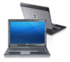
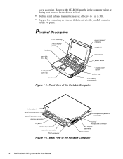
Physical Description LCD assembly status display panel keyboard hard-disk drive bay power/suspend indicator latch (2) microphone power button touch pad button (2) touch pad display close button options bay main-battery ... to 1 m (3.3 ft). • Support for connecting an external diskette drive to the parallel connector on the I /O panel service tag number expansion connector PS/2 connector headphones/speakers connector external microphone connector AC adapter connector PC Card slots Figure 1-2. Front View of the Portable Computer 1-2 Dell Latitude LM Systems Service Manual
Physical Description LCD assembly status display panel keyboard hard-disk drive bay power/suspend indicator latch (2) microphone power button touch pad button (2) touch pad display close button options bay main-battery ... to 1 m (3.3 ft). • Support for connecting an external diskette drive to the parallel connector on the I /O panel service tag number expansion connector PS/2 connector headphones/speakers connector external microphone connector AC adapter connector PC Card slots Figure 1-2. Front View of the Portable Computer 1-2 Dell Latitude LM Systems Service Manual

Service Manual
Page 13
...is located directly above the keyboard. Caps Lock Indicator Press to activate this feature. Press to activate this feature. CD-ROM/Hard-Disk Drive Indicator This indicator blinks when data is active. Press again to activate this feature. Scroll Lock Indicator Press to deactivate this feature.... System Overview 1-3 Press again to or from the CD-ROM or hard-disk drive. Pad Lock Indicator This indicator appears when the embedded keypad is being transferred to deactivate this feature. Suspend Mode When all ...
...is located directly above the keyboard. Caps Lock Indicator Press to activate this feature. Press to activate this feature. CD-ROM/Hard-Disk Drive Indicator This indicator blinks when data is active. Press again to activate this feature. Scroll Lock Indicator Press to deactivate this feature.... System Overview 1-3 Press again to or from the CD-ROM or hard-disk drive. Pad Lock Indicator This indicator appears when the embedded keypad is being transferred to deactivate this feature. Suspend Mode When all ...
Service Manual
Page 16
...closed and an external monitor is charged while the computer uses AC power. When activated, each power conservation feature turns off the hard-disk drive - The power conservation features are not being used. NOTE: To conserve power when the computer is available to -disk mode...idle. The computer automatically turns the hard-disk drive back on the built-in the status display panel blinks every 4 seconds. The Power Menu of the display, press any key on the next time the microprocessor accesses the drive. 1-6 Dell Latitude LM Systems Service Manual To increase the ...
...closed and an external monitor is charged while the computer uses AC power. When activated, each power conservation feature turns off the hard-disk drive - The power conservation features are not being used. NOTE: To conserve power when the computer is available to -disk mode...idle. The computer automatically turns the hard-disk drive back on the built-in the status display panel blinks every 4 seconds. The Power Menu of the display, press any key on the next time the microprocessor accesses the drive. 1-6 Dell Latitude LM Systems Service Manual To increase the ...

Service Manual
Page 17
... controller Used by the infrared port (COM2) Used by the serial port (COM1) Used by the audio controller Generated by the diskette drive controller to indicate that the diskette drive requires the attention of the microprocessor Used by the parallel port Generated by the system RTC Software redirect to INTOA Reserved Reserved... the output buffer of the integrated touch pad or external PS/2 mouse is full Used by the math coprocessor on the microprocessor Generated by the hard-disk drive to indicate that the drive requires the attention of the microprocessor Reserved System Overview 1-7
... controller Used by the infrared port (COM2) Used by the serial port (COM1) Used by the audio controller Generated by the diskette drive controller to indicate that the diskette drive requires the attention of the microprocessor Used by the parallel port Generated by the system RTC Software redirect to INTOA Reserved Reserved... the output buffer of the integrated touch pad or external PS/2 mouse is full Used by the math coprocessor on the microprocessor Generated by the hard-disk drive to indicate that the drive requires the attention of the microprocessor Reserved System Overview 1-7
Service Manual
Page 23
... 50°C (-4° to 122°F) Physical (Computer) Height 49.5 mm (1.95 inches) Width 299.9 mm (11.8 inches) Depth 228.7 mm (8.93 inches) Weight (with hard-disk drive, diskette drive, battery, and two PC Card blanks): Dell Latitude LM P100SD 3.1 kg (6.9 lb) Dell Latitude LM P133ST 3.1 kg (6.9 lb) System Overview 1-13 Table 1-2.
... 50°C (-4° to 122°F) Physical (Computer) Height 49.5 mm (1.95 inches) Width 299.9 mm (11.8 inches) Depth 228.7 mm (8.93 inches) Weight (with hard-disk drive, diskette drive, battery, and two PC Card blanks): Dell Latitude LM P100SD 3.1 kg (6.9 lb) Dell Latitude LM P133ST 3.1 kg (6.9 lb) System Overview 1-13 Table 1-2.

Service Manual
Page 24
... to a pulse width of 2 ms) Altitude: Operating 0 m to 2438 m (0 ft to 8,000 ft) Storage 0 m to 12,192 m (0 ft to 40,000 ft) 2 Measured with the hard-disk drive in head-parked position. 1-14 Dell Latitude LM Systems Service Manual Table 1-2.
... to a pulse width of 2 ms) Altitude: Operating 0 m to 2438 m (0 ft to 8,000 ft) Storage 0 m to 12,192 m (0 ft to 40,000 ft) 2 Measured with the hard-disk drive in head-parked position. 1-14 Dell Latitude LM Systems Service Manual Table 1-2.

Service Manual
Page 25
... incorrect key combination or entering a command incorrectly. Yes. Observe the user to determine whether he or she is making any data on the hard-disk drive if the com- Dell recommends that can often indicate the cause of computer Initial Procedures 2-1 Initial User Contact When you first contact a user who has a problem, ask...
... incorrect key combination or entering a command incorrectly. Yes. Observe the user to determine whether he or she is making any data on the hard-disk drive if the com- Dell recommends that can often indicate the cause of computer Initial Procedures 2-1 Initial User Contact When you first contact a user who has a problem, ask...

Service Manual
Page 28
...next section, "Eliminating Resource Conflicts." 2-4 Dell Latitude LM Systems Service Manual This beep is running, observe the computer for the Diagnostics Menu of a beep code. • Any unusual sounds 5. Do these indicators fails to or from the drives. Troubleshoot the power subsystem. 4. While... of these indicators light up and remain on the display? Yes. If either of the following: • Diskette-drive and hard-disk drive access indicator activity These indicators light in the status display panel, some indicators should light up within seconds after the ...
...next section, "Eliminating Resource Conflicts." 2-4 Dell Latitude LM Systems Service Manual This beep is running, observe the computer for the Diagnostics Menu of a beep code. • Any unusual sounds 5. Do these indicators fails to or from the drives. Troubleshoot the power subsystem. 4. While... of these indicators light up and remain on the display? Yes. If either of the following: • Diskette-drive and hard-disk drive access indicator activity These indicators light in the status display panel, some indicators should light up within seconds after the ...

Service Manual
Page 33
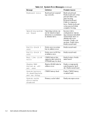
...Failing bits: nnnn Memory failed at memory address nnnn. Fixed disk 0 failure Hard-disk drive not responding to commands from computer. Fixed disk controller failure Hard-disk drive or controller not responding to commands from computer. Faulty main board. Faulty keyboard...or during normal computer operation. seated memory mod- Corrupted hard-disk drive boot sector or configuration file. ule. Faulty main board. Incorrect drive configuration. Faulty or incorrectly inserted diskette in drive. Beep Codes and Error Messages 3-3 Faulty or improperly ...
...Failing bits: nnnn Memory failed at memory address nnnn. Fixed disk 0 failure Hard-disk drive not responding to commands from computer. Fixed disk controller failure Hard-disk drive or controller not responding to commands from computer. Faulty main board. Faulty keyboard...or during normal computer operation. seated memory mod- Corrupted hard-disk drive boot sector or configuration file. ule. Faulty main board. Incorrect drive configuration. Faulty or incorrectly inserted diskette in drive. Beep Codes and Error Messages 3-3 Faulty or improperly ...
Service Manual
Page 34
... harddisk drive or on hard-disk drive or diskette drive not bootable. Faulty main board. Real time clock error CMOS battery that Faulty battery. System cache error-cache disabled Primary cache failed. NVRAM may be found Operating system cannot be dead. Faulty connections. Faulty drive. Table 3-2. Built-in main board. Faulty main board. Faulty microprocessor. 3-4 Dell Latitude LM...
... harddisk drive or on hard-disk drive or diskette drive not bootable. Faulty main board. Real time clock error CMOS battery that Faulty battery. System cache error-cache disabled Primary cache failed. NVRAM may be found Operating system cannot be dead. Faulty connections. Faulty drive. Table 3-2. Built-in main board. Faulty main board. Faulty microprocessor. 3-4 Dell Latitude LM...

Service Manual
Page 36
..., followed by a message indicating that the diagnostics is detected, a message appears on the computer. Running the Dell Diagnostics CAUTION: To prevent damage to Dell Latitude LM computers. • Network Interface - Tests the IDE hard-disk drive subsystem • IDE CD ROM Drives - Tests the serial communications port • Parallel Ports - Runs all tests for loading the diagnostics...
..., followed by a message indicating that the diagnostics is detected, a message appears on the computer. Running the Dell Diagnostics CAUTION: To prevent damage to Dell Latitude LM computers. • Network Interface - Tests the IDE hard-disk drive subsystem • IDE CD ROM Drives - Tests the serial communications port • Parallel Ports - Runs all tests for loading the diagnostics...

Service Manual
Page 40
... the computer right side up. device back of the computer. Turn the computer over and remove screws HD1 and HD2. Options Bay Lock and Latch 4-4 Dell Latitude LM Systems Service Manual Using the handle on the front of the hard-disk drive, pull the drive straight out of the computer lock latch Figure 4-5.
... the computer right side up. device back of the computer. Turn the computer over and remove screws HD1 and HD2. Options Bay Lock and Latch 4-4 Dell Latitude LM Systems Service Manual Using the handle on the front of the hard-disk drive, pull the drive straight out of the computer lock latch Figure 4-5.

Service Manual
Page 43
power/ suspend indicator heat sink LCD panel assembly latch (2) keyboard bottom assembly diskette drive, secondary battery, or CD-ROM hard-disk drive main battery Figure 4-9. Exploded Views of Components and Assemblies . Exploded View-Computer Removing and Replacing Parts 4-7
power/ suspend indicator heat sink LCD panel assembly latch (2) keyboard bottom assembly diskette drive, secondary battery, or CD-ROM hard-disk drive main battery Figure 4-9. Exploded Views of Components and Assemblies . Exploded View-Computer Removing and Replacing Parts 4-7

Service Manual
Page 49
... Part or Assembly Name Order Name Hard-Disk Drive Assemblies Hard-disk drive, 540-MB, service CUS,HD,540MB,I,F2,12.5MM,NBK kit* Hard-disk drive, subassembly, SUBASSY,HD,540MB,LF2, 540-MB 12.5MM,NBK Hard-disk drive, 540-MB HD,540MB,I,F2,12.5MM,NBK Bracket, hard-disk drive BRKT,HD,12.5MM,LMP Screws,...bracket SCR,3X.5X3,FLH,PNH,MS,ZPS,HD Hard-disk drive, 1.4-GB, service kit* CUS,HD,1.4GB,12.5MM,NN,#1, NBK Hard-disk drive, 1.4-GB SUBASSY,HD,1.4GB,12.5MM,NN, NBK Hard-disk drive, 1.4-GB HD,1.4GB,I,F2,12.5MM,NN,#1, NBK Bracket, hard-disk drive BRKT,HD,12.5MM,NBK Screws, bracket SCR...
... Part or Assembly Name Order Name Hard-Disk Drive Assemblies Hard-disk drive, 540-MB, service CUS,HD,540MB,I,F2,12.5MM,NBK kit* Hard-disk drive, subassembly, SUBASSY,HD,540MB,LF2, 540-MB 12.5MM,NBK Hard-disk drive, 540-MB HD,540MB,I,F2,12.5MM,NBK Bracket, hard-disk drive BRKT,HD,12.5MM,LMP Screws,...bracket SCR,3X.5X3,FLH,PNH,MS,ZPS,HD Hard-disk drive, 1.4-GB, service kit* CUS,HD,1.4GB,12.5MM,NN,#1, NBK Hard-disk drive, 1.4-GB SUBASSY,HD,1.4GB,12.5MM,NN, NBK Hard-disk drive, 1.4-GB HD,1.4GB,I,F2,12.5MM,NN,#1, NBK Bracket, hard-disk drive BRKT,HD,12.5MM,NBK Screws, bracket SCR...

Service Manual
Page 50
...,32M,LMP Memory module, two 16-MB DIMM,16MB,LXP Miscellaneous Parts Cover, front, hard-disk drive BZL,HDD,LMP Cover, hinge/infrared lens, right CVR,PLSTC,IR,LMP Cover, hinge, left CVR,HNG,LF,LMP Cover, keyboard screws CVR,SCR,KYBD,LMP * Customer-replaceable unit (CRU) 4-14 Dell Latitude LM Systems Service Manual Table 4-1.
...,32M,LMP Memory module, two 16-MB DIMM,16MB,LXP Miscellaneous Parts Cover, front, hard-disk drive BZL,HDD,LMP Cover, hinge/infrared lens, right CVR,PLSTC,IR,LMP Cover, hinge, left CVR,HNG,LF,LMP Cover, keyboard screws CVR,SCR,KYBD,LMP * Customer-replaceable unit (CRU) 4-14 Dell Latitude LM Systems Service Manual Table 4-1.

Service Manual
Page 51
...,DCKG,LMP Insulator, main board INSUL,MYLAR,I/O,LMP Bracket, I/O BRKT,I/O,LMP Door, I/O DOOR,I/O,LMP Door, memory module DOOR,RAM,LMP Guide, hard-disk drive, left GDE,RL,LF,HD,LMP Assembly, base CVR,BTM,PLSTC,SYS,BAS,LMP Door, expansion connector (docking DOOR,DCKG,LMP port) Screws Screw...ZPS Screw, expansion connector (dock- SCR,CON,JK,DCKG,LMP ing port) standoff Service Documentation Service Manual MNL,SERVICE,LMP Technical sheet, hard-disk drive TSH,HD,LMP,ENG Technical sheet, options bay TSH,OPT,BAY,LMP,ENG Technical sheet, AC adapter TSH,AC ADAPT,LMP,ENG Technical ...
...,DCKG,LMP Insulator, main board INSUL,MYLAR,I/O,LMP Bracket, I/O BRKT,I/O,LMP Door, I/O DOOR,I/O,LMP Door, memory module DOOR,RAM,LMP Guide, hard-disk drive, left GDE,RL,LF,HD,LMP Assembly, base CVR,BTM,PLSTC,SYS,BAS,LMP Door, expansion connector (docking DOOR,DCKG,LMP port) Screws Screw...ZPS Screw, expansion connector (dock- SCR,CON,JK,DCKG,LMP ing port) standoff Service Documentation Service Manual MNL,SERVICE,LMP Technical sheet, hard-disk drive TSH,HD,LMP,ENG Technical sheet, options bay TSH,OPT,BAY,LMP,ENG Technical sheet, AC adapter TSH,AC ADAPT,LMP,ENG Technical ...

Reference and Troubleshooting Guide
Page 125
See hard-disk drive hard-disk drive testing, 4-17 troubleshooting, 3-15 Hard-Disk Drives (Non-SCSI) Test Group Dell diagnostics, 4-17 help from Dell Computer Corporation, 5-1 help , 5-1 graphics mode screens, B-4 Graphics Mode Test, B-4 grounding procedure, vii H hard drive. See IRQ IRQ lines, 3-10 K keyboard checking external keyboard during POST, 3-16 Keyboard Test Group in Dell diagnostics, 4-15 Keyboard Test Group Dell diagnostics, 4-15...
See hard-disk drive hard-disk drive testing, 4-17 troubleshooting, 3-15 Hard-Disk Drives (Non-SCSI) Test Group Dell diagnostics, 4-17 help from Dell Computer Corporation, 5-1 help , 5-1 graphics mode screens, B-4 Graphics Mode Test, B-4 grounding procedure, vii H hard drive. See IRQ IRQ lines, 3-10 K keyboard checking external keyboard during POST, 3-16 Keyboard Test Group in Dell diagnostics, 4-15 Keyboard Test Group Dell diagnostics, 4-15...


