
Service Manual
Page 3
Contents Chapter 1 System Overview 1-1 System Features 1-1 Physical Description 1-2 Status Display 1-3 Keyboard Indicators 1-3 CD-ROM/Hard-Disk Drive Indicator 1-3 Diskette-Drive Access Indicator 1-4 PC Card Indicator 1-4 AC Power Indicator 1-4 Battery Activity Indicator 1-4 Battery Status Indicator 1-4 Battery Charge Gauge 1-5 Password 1-5 System ...
Contents Chapter 1 System Overview 1-1 System Features 1-1 Physical Description 1-2 Status Display 1-3 Keyboard Indicators 1-3 CD-ROM/Hard-Disk Drive Indicator 1-3 Diskette-Drive Access Indicator 1-4 PC Card Indicator 1-4 AC Power Indicator 1-4 Battery Activity Indicator 1-4 Battery Status Indicator 1-4 Battery Charge Gauge 1-5 Password 1-5 System ...

Service Manual
Page 4
... 3-1 System Error Messages 3-3 Running the Dell Diagnostics 3-6 Chapter 4 Removing and Replacing Parts 4-1 Recommended Tools 4-1 Screw Identification and Tightening 4-2 Precautionary Measures 4-3 ZIF Connectors 4-6 Exploded Views of Components and Assemblies 4-7 Factory Repair Parts and Assemblies 4-11 Deleting the Password 4-18 Hard-Disk Drive 4-19 Diskette Drive 4-20 CD-ROM 4-21 Memory Module 4-22 LCD Assembly...
... 3-1 System Error Messages 3-3 Running the Dell Diagnostics 3-6 Chapter 4 Removing and Replacing Parts 4-1 Recommended Tools 4-1 Screw Identification and Tightening 4-2 Precautionary Measures 4-3 ZIF Connectors 4-6 Exploded Views of Components and Assemblies 4-7 Factory Repair Parts and Assemblies 4-11 Deleting the Password 4-18 Hard-Disk Drive 4-19 Diskette Drive 4-20 CD-ROM 4-21 Memory Module 4-22 LCD Assembly...

Service Manual
Page 5
... 4-20. Main Battery Removal 4-3 Figure 4-4. Screw Identification 4-2 Figure 4-3. Speakers Removal 4-34 Figure 4-28. Exploded View-Bottom Assembly 4-10 Figure 4-13. Diskette Drive, Secondary Battery, or CD-ROM Removal. . . 4-5 Figure 4-7. CD-ROM Assembly 4-21 Figure 4-17.
... 4-20. Main Battery Removal 4-3 Figure 4-4. Screw Identification 4-2 Figure 4-3. Speakers Removal 4-34 Figure 4-28. Exploded View-Bottom Assembly 4-10 Figure 4-13. Diskette Drive, Secondary Battery, or CD-ROM Removal. . . 4-5 Figure 4-7. CD-ROM Assembly 4-21 Figure 4-17.
Service Manual
Page 11
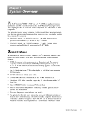
... computer. processor and an SVGA (S) dual-scan (D) STN LCD. • The Dell Latitude LM P-133ST contains a 133-MHz Pentium micro- This feature is sometimes called System Overview 1-1 The CD-ROM can be inserted or removed while the computer is sometimes called hot swapping. The individual... model names within the Dell Latitude LM portable family indicate the type and operating frequency of the microprocessor and...
... computer. processor and an SVGA (S) dual-scan (D) STN LCD. • The Dell Latitude LM P-133ST contains a 133-MHz Pentium micro- This feature is sometimes called System Overview 1-1 The CD-ROM can be inserted or removed while the computer is sometimes called hot swapping. The individual... model names within the Dell Latitude LM portable family indicate the type and operating frequency of the microprocessor and...
Service Manual
Page 12
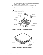
warm swapping. Front View of the Portable Computer 1-2 Dell Latitude LM Systems Service Manual Physical Description LCD assembly status display panel keyboard hard-disk drive bay power/suspend indicator latch (2) microphone power button touch pad button... main-battery compartment Figure 1-1. Back View of the Portable Computer infrared port serial port connector parallel port connector monitor connector I /O panel. However, the CD-ROM must be in the computer before or during boot in order for the drivers to load. • Built-in serial infrared transmitter/receiver, effective to...
warm swapping. Front View of the Portable Computer 1-2 Dell Latitude LM Systems Service Manual Physical Description LCD assembly status display panel keyboard hard-disk drive bay power/suspend indicator latch (2) microphone power button touch pad button... main-battery compartment Figure 1-1. Back View of the Portable Computer infrared port serial port connector parallel port connector monitor connector I /O panel. However, the CD-ROM must be in the computer before or during boot in order for the drivers to load. • Built-in serial infrared transmitter/receiver, effective to...

Service Manual
Page 13
... . Suspend Mode When all indicators are present and appear to be rolling the computer is being transferred to activate this feature. CD-ROM/Hard-Disk Drive Indicator This indicator blinks when data is in suspend mode. This panel shows icons that indicate keyboard operation or ...suspend mode; Status Display . Figure 1-3. Pad Lock Indicator This indicator appears when the embedded keypad is active. CD-ROM, hard-disk drive, diskette drive, and PC Card activity; Press again to activate this feature. Scroll Lock Indicator Press to deactivate this...
... . Suspend Mode When all indicators are present and appear to be rolling the computer is being transferred to activate this feature. CD-ROM/Hard-Disk Drive Indicator This indicator blinks when data is in suspend mode. This panel shows icons that indicate keyboard operation or ...suspend mode; Status Display . Figure 1-3. Pad Lock Indicator This indicator appears when the embedded keypad is active. CD-ROM, hard-disk drive, diskette drive, and PC Card activity; Press again to activate this feature. Scroll Lock Indicator Press to deactivate this...

Service Manual
Page 36
...and then turn on the screen telling you choose the following test groups: • RAM - If a main memory error is needed to Dell Latitude LM computers. Tests the operation of the main board • Video - Tests a SCSI hard-disk drive subsystem NOTE: This test does not... apply to the original diagnostics diskette, always use a backup copy of the diagnostics diskette when servicing a user's computer. Tests a CD-ROM drive subsystem • Serial/Infrared Ports - Before the diagnostics loads, a program tests the portion of this diskette to appear, followed by a...
...and then turn on the screen telling you choose the following test groups: • RAM - If a main memory error is needed to Dell Latitude LM computers. Tests the operation of the main board • Video - Tests a SCSI hard-disk drive subsystem NOTE: This test does not... apply to the original diagnostics diskette, always use a backup copy of the diagnostics diskette when servicing a user's computer. Tests a CD-ROM drive subsystem • Serial/Infrared Ports - Before the diagnostics loads, a program tests the portion of this diskette to appear, followed by a...

Service Manual
Page 40
... Options Bay Lock and Latch 4-4 Dell Latitude LM Systems Service Manual Turn the computer over and remove screws HD1 and HD2. device back of the computer. handle cover HD1 HD2 Figure 4-4. This feature is sometimes called hot swapping. However, the CD-ROM must be inserted or removed while ...and HD2 are 10 mm) 10mm 6. Remove the hard-disk drive assembly. Remove the diskette drive, secondary battery, or CD-ROM from the computer. The CD-ROM can be in the computer before or during boot in suspend mode. This feature is sometimes called warm swapping. Slide the...
... Options Bay Lock and Latch 4-4 Dell Latitude LM Systems Service Manual Turn the computer over and remove screws HD1 and HD2. device back of the computer. handle cover HD1 HD2 Figure 4-4. This feature is sometimes called hot swapping. However, the CD-ROM must be inserted or removed while ...and HD2 are 10 mm) 10mm 6. Remove the hard-disk drive assembly. Remove the diskette drive, secondary battery, or CD-ROM from the computer. The CD-ROM can be in the computer before or during boot in suspend mode. This feature is sometimes called warm swapping. Slide the...

Service Manual
Page 41
Figure 4-7. PC Card Removal Removing and Replacing Parts 4-5 If you are removing a type III card, press the bottom eject button. Diskette Drive, Secondary Battery, or CD-ROM Removal 7. To remove a PC Card from the top connector, press the top eject button (identified by an arrow pointing down). Figure 4-6. Remove any PC Cards ... bottom eject button (identified by an arrow pointing up). Keep holding the latch with one hand while pulling the device (diskette drive, secondary battery, or CD-ROM) straight out of the options bay with the other.
Figure 4-7. PC Card Removal Removing and Replacing Parts 4-5 If you are removing a type III card, press the bottom eject button. Diskette Drive, Secondary Battery, or CD-ROM Removal 7. To remove a PC Card from the top connector, press the top eject button (identified by an arrow pointing down). Figure 4-6. Remove any PC Cards ... bottom eject button (identified by an arrow pointing up). Keep holding the latch with one hand while pulling the device (diskette drive, secondary battery, or CD-ROM) straight out of the options bay with the other.

Service Manual
Page 43
Exploded Views of Components and Assemblies . Exploded View-Computer Removing and Replacing Parts 4-7 power/ suspend indicator heat sink LCD panel assembly latch (2) keyboard bottom assembly diskette drive, secondary battery, or CD-ROM hard-disk drive main battery Figure 4-9.
Exploded Views of Components and Assemblies . Exploded View-Computer Removing and Replacing Parts 4-7 power/ suspend indicator heat sink LCD panel assembly latch (2) keyboard bottom assembly diskette drive, secondary battery, or CD-ROM hard-disk drive main battery Figure 4-9.

Service Manual
Page 48
...,CNTRL,SPKR,LMP Board, infrared CRD,IR,LMP Board, audio CRD,AUDIO,LMP Cable, audio board CBL,FLEX,JK,AUD,LMP CD-ROM CD-ROM, service kit* CUS,CD ROM,4X,LMP,SANYO CD-ROM drive CD ROM,4X,LMP,SANYO Diskette Drive Assembly Diskette drive assembly* CUST,FD,INT/EXT,LMP Diskette drive, internal/external FD,INT/EXT,LMP... PLSTC,LWR,FD,LMP Cable, service kit* CUST,CBL,FD,INT/EXT,LMP Connector, cable CBL,FD,INT/EXT,LMP * Customer-replaceable unit (CRU) 4-12 Dell Latitude LM Systems Service Manual
...,CNTRL,SPKR,LMP Board, infrared CRD,IR,LMP Board, audio CRD,AUDIO,LMP Cable, audio board CBL,FLEX,JK,AUD,LMP CD-ROM CD-ROM, service kit* CUS,CD ROM,4X,LMP,SANYO CD-ROM drive CD ROM,4X,LMP,SANYO Diskette Drive Assembly Diskette drive assembly* CUST,FD,INT/EXT,LMP Diskette drive, internal/external FD,INT/EXT,LMP... PLSTC,LWR,FD,LMP Cable, service kit* CUST,CBL,FD,INT/EXT,LMP Connector, cable CBL,FD,INT/EXT,LMP * Customer-replaceable unit (CRU) 4-12 Dell Latitude LM Systems Service Manual

Service Manual
Page 57
Removing and Replacing Parts 4-21 CD-ROM CD-ROM and carrier Figure 4-16. CD-ROM Assembly The CD-ROM resides in a carrier that slides into the options drive bay on the right side of the computer. The CD-ROM and carrier are replaced as a unit and are not disassembled.
Removing and Replacing Parts 4-21 CD-ROM CD-ROM and carrier Figure 4-16. CD-ROM Assembly The CD-ROM resides in a carrier that slides into the options drive bay on the right side of the computer. The CD-ROM and carrier are replaced as a unit and are not disassembled.

Service Manual
Page 83
... removal, 4-43 boot routine observing when troubleshooting, 2-3 bottom assembly, 4-39 C cache board removal, 4-45 Caps Lock indicator, 1-3 CD-ROM disassembly, 4-21 CD-ROM/Hard-Disk Drive indicator, 1-3 computer features, 1-1 illustrated, 1-2 power conservation modes, 1-6 technical specifications, 1-8 computer power, 1-6 D Dell diagnostics, 3-6 dimming the display, 1-6 diskette drive bay, 1-2 diskette drive disassembly, 4-20 diskette drive removal, 4-4 diskette-based diagnostics...
... removal, 4-43 boot routine observing when troubleshooting, 2-3 bottom assembly, 4-39 C cache board removal, 4-45 Caps Lock indicator, 1-3 CD-ROM disassembly, 4-21 CD-ROM/Hard-Disk Drive indicator, 1-3 computer features, 1-1 illustrated, 1-2 power conservation modes, 1-6 technical specifications, 1-8 computer power, 1-6 D Dell diagnostics, 3-6 dimming the display, 1-6 diskette drive bay, 1-2 diskette drive disassembly, 4-20 diskette drive removal, 4-4 diskette-based diagnostics...

Service Manual Update
Page 1
... with MMX™ technology in the Dell Latitude LM M166ST, which has the same features as other models of the computer. • Support for a video subsystem that includes 1.1 MB of video memory. • 6X or 10X CD-ROM drives. • Your computer may have been added. Dell ®Latitude® LM Service Manual Update This document updates information... on the main board. (The standard minimum configuration is now 8 MB of nonremovable memory on the main board and two 4-MB memory modules in the Dell Latitude LM Service Manual.
... with MMX™ technology in the Dell Latitude LM M166ST, which has the same features as other models of the computer. • Support for a video subsystem that includes 1.1 MB of video memory. • 6X or 10X CD-ROM drives. • Your computer may have been added. Dell ®Latitude® LM Service Manual Update This document updates information... on the main board. (The standard minimum configuration is now 8 MB of nonremovable memory on the main board and two 4-MB memory modules in the Dell Latitude LM Service Manual.

Service Manual Update
Page 3
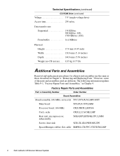
Dell Latitude LM Service Manual Update 3 Technical Specifications (continued) Video Video type 64-bit (128-bit hardware accelerated) PCI Video controller NeoMagic 2093 (systems with MMX technology) or ... cycles Temperature range: Charge and discharge . . . . 5° to 35°C (41° to 95°F) Storage 20° to 50°C (-4° to 122°F) CD-ROM Drive Form factor 5.25 inches Interface IDE Memory 128,000 bytes (data buffer memory) * Battery performance features such as charge time, operating time, and life...
Dell Latitude LM Service Manual Update 3 Technical Specifications (continued) Video Video type 64-bit (128-bit hardware accelerated) PCI Video controller NeoMagic 2093 (systems with MMX technology) or ... cycles Temperature range: Charge and discharge . . . . 5° to 35°C (41° to 95°F) Storage 20° to 50°C (-4° to 122°F) CD-ROM Drive Form factor 5.25 inches Interface IDE Memory 128,000 bytes (data buffer memory) * Battery performance features such as charge time, operating time, and life...
Service Manual Update
Page 4
...CD-ROM Drive (continued) Voltage 5 V (single-voltage drive) Access time 250 m/sec Data transfer rate: Sequential 150 KB/sec 900 KB/sec (6X) 1500 KB/sec (10X) From buffer 14.4 MB/sec Physical: Height 17.0 mm (0.67 inch) Width 130.6 mm (5.14 inches) Depth 140.6 mm (5.56 inches) Weight (no CD...SUBASSY,HTSNK,CPU,LMM Screws, heat sink SCR,2X,4X4,PHH,MS,ZPS Spacer/Bumper, rubber, flex cable BMPR,LCD,FPC,25X5X5M,LMP 4 Dell Latitude LM Service Manual Update However, some of the parts and assemblies used are the same as those described in Chapter 4. The following information updates Table ...
...CD-ROM Drive (continued) Voltage 5 V (single-voltage drive) Access time 250 m/sec Data transfer rate: Sequential 150 KB/sec 900 KB/sec (6X) 1500 KB/sec (10X) From buffer 14.4 MB/sec Physical: Height 17.0 mm (0.67 inch) Width 130.6 mm (5.14 inches) Depth 140.6 mm (5.56 inches) Weight (no CD...SUBASSY,HTSNK,CPU,LMM Screws, heat sink SCR,2X,4X4,PHH,MS,ZPS Spacer/Bumper, rubber, flex cable BMPR,LCD,FPC,25X5X5M,LMP 4 Dell Latitude LM Service Manual Update However, some of the parts and assemblies used are the same as those described in Chapter 4. The following information updates Table ...

Service Manual Update
Page 5
...DC,LMP Boards and Cards Cable, flex, audio jack CBL,FLEX,JK,AUD,W/EMI,LM CD-ROM CD-ROM, service kit* CUS,CD ROM,6X,LMP CD-ROM drive CD ROM,6X,LMP CD-ROM, service kit* CUS,CD ROM,I,INT,10X,LMP CD-ROM drive CD ROM,I,INT,10X,LM Hard-Disk Drive Assemblies Hard-disk drive, 2.1-GB, service kit* CUS,HD,2.1GB,I,.../INV,TFT,LMM,IBM Cable, TFT flex CBL,FLEX,LCD,TFT,IBM,W/ EMI,LM LCD, SA, service kit SVC,LCD/FPC/INV,TFT,LMM, SMSNG LCD panel, active-matrix color display (TFT), 12.1" LCD,TFT,SVGA,12.1",LM,SMSNG * Customer-replaceable unit (CRU) Dell Latitude LM Service Manual Update 5
...DC,LMP Boards and Cards Cable, flex, audio jack CBL,FLEX,JK,AUD,W/EMI,LM CD-ROM CD-ROM, service kit* CUS,CD ROM,6X,LMP CD-ROM drive CD ROM,6X,LMP CD-ROM, service kit* CUS,CD ROM,I,INT,10X,LMP CD-ROM drive CD ROM,I,INT,10X,LM Hard-Disk Drive Assemblies Hard-disk drive, 2.1-GB, service kit* CUS,HD,2.1GB,I,.../INV,TFT,LMM,IBM Cable, TFT flex CBL,FLEX,LCD,TFT,IBM,W/ EMI,LM LCD, SA, service kit SVC,LCD/FPC/INV,TFT,LMM, SMSNG LCD panel, active-matrix color display (TFT), 12.1" LCD,TFT,SVGA,12.1",LM,SMSNG * Customer-replaceable unit (CRU) Dell Latitude LM Service Manual Update 5

Reference and Troubleshooting Guide
Page 11
Contents Chapter 1 Introduction 1-1 Hardware Features 1-2 Software Features 1-3 Accessing Online Documentation 1-4 Available Options 1-4 Getting Help 1-4 Chapter 2 Customizing System Features 2-1 System Utilities 2-1 Setup Program 2-2 Accessing the Setup Program 2-2 Main Menu Options 2-2 Date 2-3 Time 2-3 Hard-Disk Drive 0 2-3 Boot Sequence 2-3 Diskette A 2-4 Total Memory 2-4 Video Memory 2-4 Peripherals Menu Options 2-4 Integrated Peripherals 2-4 Serial Port 2-4 Infrared 2-5 Parallel Mode 2-6 Diskette Mode 2-6 Video Mode 2-6 Touch Pad 2-6 CD-ROM Drive Speed 2-6 xiii
Contents Chapter 1 Introduction 1-1 Hardware Features 1-2 Software Features 1-3 Accessing Online Documentation 1-4 Available Options 1-4 Getting Help 1-4 Chapter 2 Customizing System Features 2-1 System Utilities 2-1 Setup Program 2-2 Accessing the Setup Program 2-2 Main Menu Options 2-2 Date 2-3 Time 2-3 Hard-Disk Drive 0 2-3 Boot Sequence 2-3 Diskette A 2-4 Total Memory 2-4 Video Memory 2-4 Peripherals Menu Options 2-4 Integrated Peripherals 2-4 Serial Port 2-4 Infrared 2-5 Parallel Mode 2-6 Diskette Mode 2-6 Video Mode 2-6 Touch Pad 2-6 CD-ROM Drive Speed 2-6 xiii

Reference and Troubleshooting Guide
Page 13
... a Battery 3-13 No Power to a Part of the Computer 3-14 Troubleshooting the Diskette Drive 3-14 Troubleshooting the CD-ROM Drive 3-15 Troubleshooting the Hard-Disk Drive 3-15 Troubleshooting an External Keyboard 3-16 Troubleshooting Memory 3-17 Troubleshooting the Built...21 Troubleshooting Audio Functions 3-22 Chapter 4 Running the Dell Diagnostics 4-1 Features of the Dell Diagnostics 4-1 When to Use the Dell Diagnostics 4-1 Before You Start Testing 4-2 Starting the Dell Diagnostics 4-2 How to Use the Dell Diagnostics 4-3 Confirming the System Configuration Information 4-4 How to...
... a Battery 3-13 No Power to a Part of the Computer 3-14 Troubleshooting the Diskette Drive 3-14 Troubleshooting the CD-ROM Drive 3-15 Troubleshooting the Hard-Disk Drive 3-15 Troubleshooting an External Keyboard 3-16 Troubleshooting Memory 3-17 Troubleshooting the Built...21 Troubleshooting Audio Functions 3-22 Chapter 4 Running the Dell Diagnostics 4-1 Features of the Dell Diagnostics 4-1 When to Use the Dell Diagnostics 4-1 Before You Start Testing 4-2 Starting the Dell Diagnostics 4-2 How to Use the Dell Diagnostics 4-3 Confirming the System Configuration Information 4-4 How to...

Reference and Troubleshooting Guide
Page 15
... Test Group 4-18 Why Run an IDE CD ROM Drives Test 4-18 Subtests 4-18 Serial/Infrared Ports Test Group 4-18 Why Run a Serial/Infrared Ports Test 4-18 Subtests 4-19 Parallel Ports... Why Run an Audio Test 4-20 Subtests 4-20 Chapter 5 Getting Help 5-1 Technical Assistance 5-1 Help Tools 5-1 Dell Q&A 5-2 System User's Guide 5-2 Reference and Troubleshooting Guide 5-2 World Wide Web on the Internet 5-2 Commercial Online Services 5-3 Dell Diagnostics Program 5-3 AutoTech Service 5-3 TechFax Service 5-3 TechConnect BBS 5-4 Automated Order-Status System 5-4 Problems With Your Order...
... Test Group 4-18 Why Run an IDE CD ROM Drives Test 4-18 Subtests 4-18 Serial/Infrared Ports Test Group 4-18 Why Run a Serial/Infrared Ports Test 4-18 Subtests 4-19 Parallel Ports... Why Run an Audio Test 4-20 Subtests 4-20 Chapter 5 Getting Help 5-1 Technical Assistance 5-1 Help Tools 5-1 Dell Q&A 5-2 System User's Guide 5-2 Reference and Troubleshooting Guide 5-2 World Wide Web on the Internet 5-2 Commercial Online Services 5-3 Dell Diagnostics Program 5-3 AutoTech Service 5-3 TechFax Service 5-3 TechConnect BBS 5-4 Automated Order-Status System 5-4 Problems With Your Order...


