
Service Manual
Page 3
... Features 1-1 Physical Description 1-2 Status Display 1-3 Keyboard Indicators 1-3 CD-ROM/Hard-Disk Drive Indicator 1-3 Diskette-Drive Access Indicator 1-4 PC Card Indicator 1-4 AC Power Indicator 1-4 Battery Activity Indicator 1-4 Battery Status Indicator 1-4 Battery Charge Gauge 1-5 Password 1-5 System Power 1-6 Power Conservation 1-6 Interrupt Assignments 1-7 Technical Specifications 1-8 Chapter 2 Initial Procedures 2-1 Initial User Contact 2-1 Visual Inspection 2-1 Observing the Boot Routine...
... Features 1-1 Physical Description 1-2 Status Display 1-3 Keyboard Indicators 1-3 CD-ROM/Hard-Disk Drive Indicator 1-3 Diskette-Drive Access Indicator 1-4 PC Card Indicator 1-4 AC Power Indicator 1-4 Battery Activity Indicator 1-4 Battery Status Indicator 1-4 Battery Charge Gauge 1-5 Password 1-5 System Power 1-6 Power Conservation 1-6 Interrupt Assignments 1-7 Technical Specifications 1-8 Chapter 2 Initial Procedures 2-1 Initial User Contact 2-1 Visual Inspection 2-1 Observing the Boot Routine...

Service Manual
Page 5
.... Power/Suspend Indicator Removal 4-28 Figure 4-24. Speakers Removal 4-34 Figure 4-28. LCD Panel Removal 4-25 Figure 4-21. Main Battery Removal 4-3 Figure 4-4. Exploded View-Bottom Assembly 4-10 Figure 4-13. CD-ROM Assembly 4-21 Figure 4-17. Status Display Board Removal.... Memory Module Removal 4-22 Figure 4-18. Capacitor C146 (Location 4-18 Figure 4-14. Top Assembly Removal 4-32 Figure 4-27. Diskette Drive, Secondary Battery, or CD-ROM Removal. . . 4-5 Figure 4-7. LCD Assembly Removal 4-23 Figure 4-19. Back View of the Portable Computer 1-2 Figure 1-2. Screw...
.... Power/Suspend Indicator Removal 4-28 Figure 4-24. Speakers Removal 4-34 Figure 4-28. LCD Panel Removal 4-25 Figure 4-21. Main Battery Removal 4-3 Figure 4-4. Exploded View-Bottom Assembly 4-10 Figure 4-13. CD-ROM Assembly 4-21 Figure 4-17. Status Display Board Removal.... Memory Module Removal 4-22 Figure 4-18. Capacitor C146 (Location 4-18 Figure 4-14. Top Assembly Removal 4-32 Figure 4-27. Diskette Drive, Secondary Battery, or CD-ROM Removal. . . 4-5 Figure 4-7. LCD Assembly Removal 4-23 Figure 4-19. Back View of the Portable Computer 1-2 Figure 1-2. Screw...
Service Manual
Page 11
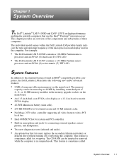
... 1-1 processor and an SVGA (S) dual-scan (D) STN LCD. • The Dell Latitude LM P-133ST contains a 133-MHz Pentium micro- Chapter 1 System Overview The Dell® Latitude® LM P-100SD and LM P-133ST are high-performance multimedia portable computers that lets users replace the secondary lithium ion battery or diskette drive without turning off or rebooting the computer. phones...
... 1-1 processor and an SVGA (S) dual-scan (D) STN LCD. • The Dell Latitude LM P-133ST contains a 133-MHz Pentium micro- Chapter 1 System Overview The Dell® Latitude® LM P-100SD and LM P-133ST are high-performance multimedia portable computers that lets users replace the secondary lithium ion battery or diskette drive without turning off or rebooting the computer. phones...
Service Manual
Page 12
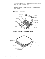
... display panel keyboard hard-disk drive bay power/suspend indicator latch (2) microphone power button touch pad button (2) touch pad display close button options bay main-battery compartment Figure 1-1. Back View of the Portable Computer infrared port serial port connector parallel port connector monitor connector I /O panel. However, the CD-ROM must... connector PS/2 connector headphones/speakers connector external microphone connector AC adapter connector PC Card slots Figure 1-2. warm swapping. Front View of the Portable Computer 1-2 Dell Latitude LM Systems Service Manual
... display panel keyboard hard-disk drive bay power/suspend indicator latch (2) microphone power button touch pad button (2) touch pad display close button options bay main-battery compartment Figure 1-1. Back View of the Portable Computer infrared port serial port connector parallel port connector monitor connector I /O panel. However, the CD-ROM must... connector PS/2 connector headphones/speakers connector external microphone connector AC adapter connector PC Card slots Figure 1-2. warm swapping. Front View of the Portable Computer 1-2 Dell Latitude LM Systems Service Manual

Service Manual
Page 13
...-ROM, hard-disk drive, diskette drive, and PC Card activity; Keyboard Indicators The following icons indicate the status of the power source (AC power or batteries). Num Lock Indicator Press to activate this feature. Pad Lock Indicator This indicator appears when the embedded keypad is in suspend mode. Press to deactivate...
...-ROM, hard-disk drive, diskette drive, and PC Card activity; Keyboard Indicators The following icons indicate the status of the power source (AC power or batteries). Num Lock Indicator Press to activate this feature. Pad Lock Indicator This indicator appears when the embedded keypad is in suspend mode. Press to deactivate...
Service Manual
Page 14
... indicator means there is present, the upper triangle appears. If the secondary battery is off. Battery Status Indicator The battery status indicator reflects the state of the main or secondary battery in the computer or, if present, the battery has been discharged. 1-4 Dell Latitude LM Systems Service Manual PC Card Indicator This indicator blinks when the computer is...
... indicator means there is present, the upper triangle appears. If the secondary battery is off. Battery Status Indicator The battery status indicator reflects the state of the main or secondary battery in the computer or, if present, the battery has been discharged. 1-4 Dell Latitude LM Systems Service Manual PC Card Indicator This indicator blinks when the computer is...

Service Manual
Page 15
...; The AC power indicator with three short, audible beeps. Each bar equals 10 percent of battery life remaining. Dell technicians will erase the password by shorting C146, recharge the CMOS battery, and send the computer back at the user's expense. For the procedure to indicate the ... An indicator with no bars means that battery power is low (about 80 percent depleted). Password CAUTION: Dell strongly recommends that the battery is too hot (40° C [104° F] or more) to Dell at the user's expense. Charging starts automatically when the battery cools to below 40° C. &#...
...; The AC power indicator with three short, audible beeps. Each bar equals 10 percent of battery life remaining. Dell technicians will erase the password by shorting C146, recharge the CMOS battery, and send the computer back at the user's expense. For the procedure to indicate the ... An indicator with no bars means that battery power is low (about 80 percent depleted). Password CAUTION: Dell strongly recommends that the battery is too hot (40° C [104° F] or more) to Dell at the user's expense. Charging starts automatically when the battery cools to below 40° C. &#...
Service Manual
Page 16
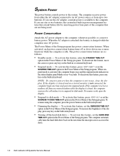
...panel blinks every 4 seconds. To resume using the computer, press the power button on the next time the microprocessor accesses the drive. 1-6 Dell Latitude LM Systems Service Manual If you use , close the display. To activate this feature, press or set the HARD-DISK TIME-OUT option in... select the STANDBY TIME-OUT option in or external keyboard. • Suspend mode - System Power The power button controls power to conserve battery power. Power Conservation Attach the AC power adapter to the computer, whenever possible, to the system. When suspend mode is not connected, the...
...panel blinks every 4 seconds. To resume using the computer, press the power button on the next time the microprocessor accesses the drive. 1-6 Dell Latitude LM Systems Service Manual If you use , close the display. To activate this feature, press or set the HARD-DISK TIME-OUT option in... select the STANDBY TIME-OUT option in or external keyboard. • Suspend mode - System Power The power button controls power to conserve battery power. Power Conservation Attach the AC power adapter to the computer, whenever possible, to the system. When suspend mode is not connected, the...

Service Manual
Page 22
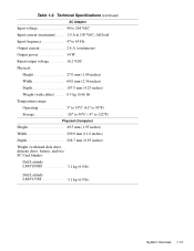
...):1 Computer on 4 hours Computer off 3 hours Operating time (approximate, with no power management features enabled):1 3 to 5 hours with one battery; 6 to 10 hours with two batteries Life span (approximate)1 . . . . 500 discharge/charge cycles Temperature range: Charge 0° to 40°C (32° to ...32° to 140°F) Storage 20° to 50°C (-4° to 122°F) 1 Battery performance features such as charge time, operating time, and life span can vary according to the conditions under which the computer and battery are used. 1-12 Dell Latitude LM Systems Service Manual
...):1 Computer on 4 hours Computer off 3 hours Operating time (approximate, with no power management features enabled):1 3 to 5 hours with one battery; 6 to 10 hours with two batteries Life span (approximate)1 . . . . 500 discharge/charge cycles Temperature range: Charge 0° to 40°C (32° to ...32° to 140°F) Storage 20° to 50°C (-4° to 122°F) 1 Battery performance features such as charge time, operating time, and life span can vary according to the conditions under which the computer and battery are used. 1-12 Dell Latitude LM Systems Service Manual
Service Manual
Page 23
...°F) Physical (Computer) Height 49.5 mm (1.95 inches) Width 299.9 mm (11.8 inches) Depth 228.7 mm (8.93 inches) Weight (with hard-disk drive, diskette drive, battery, and two PC Card blanks): Dell Latitude LM P100SD 3.1 kg (6.9 lb) Dell Latitude LM P133ST 3.1 kg (6.9 lb) System Overview 1-13
...°F) Physical (Computer) Height 49.5 mm (1.95 inches) Width 299.9 mm (11.8 inches) Depth 228.7 mm (8.93 inches) Weight (with hard-disk drive, diskette drive, battery, and two PC Card blanks): Dell Latitude LM P100SD 3.1 kg (6.9 lb) Dell Latitude LM P133ST 3.1 kg (6.9 lb) System Overview 1-13

Service Manual
Page 26
...damage, and then reinstall the modules. 9. If the display is not in the following : a. The AC adapter's LED should be on each battery to step 3. 3. Open the computer, and verify that the computer is on, go to step 2. 2. If the display is off the ...of any obvious physical damage and that the touch pad and its keys operate freely. 11. Verify that its associated buttons operate freely. 2-2 Dell Latitude LM Systems Service Manual b. Then proceed to see Chapter 4, "Removing and Replacing Parts." Press the test button located on . Remove any obvious...
...damage, and then reinstall the modules. 9. If the display is not in the following : a. The AC adapter's LED should be on each battery to step 3. 3. Open the computer, and verify that the computer is on, go to step 2. 2. If the display is off the ...of any obvious physical damage and that the touch pad and its keys operate freely. 11. Verify that its associated buttons operate freely. 2-2 Dell Latitude LM Systems Service Manual b. Then proceed to see Chapter 4, "Removing and Replacing Parts." Press the test button located on . Remove any obvious...
Service Manual
Page 34
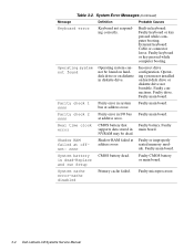
...Faulty main board. seated memory mod- Faulty drive. Faulty CMOS battery or main board. Faulty keyboard or key pressed while computer booting. System battery is dead-Replace and run Setup CMOS battery dead. Parity check 2 nnnn Parity error in keyboard: Faulty ... ule. Faulty microprocessor. 3-4 Dell Latitude LM Systems Service Manual System cache error-cache disabled Primary cache failed. External keyboard: Cable or connector loose. bus at address nnnn. Faulty main board. Real time clock error CMOS battery that Faulty battery. Operating system not found on...
...Faulty main board. seated memory mod- Faulty drive. Faulty CMOS battery or main board. Faulty keyboard or key pressed while computer booting. System battery is dead-Replace and run Setup CMOS battery dead. Parity check 2 nnnn Parity error in keyboard: Faulty ... ule. Faulty microprocessor. 3-4 Dell Latitude LM Systems Service Manual System cache error-cache disabled Primary cache failed. External keyboard: Cable or connector loose. bus at address nnnn. Faulty main board. Real time clock error CMOS battery that Faulty battery. Operating system not found on...

Service Manual
Page 39
... to reduce the potential for personal injury or shock. 3. Turn off the computer and any attached peripherals. 2. Remove the main battery from AC power sources to reduce the potential for personal injury or shock. 4. Ground yourself by touching one of the computer, ...press down on the computer, perform the following warning. Disconnect the computer and any attached peripherals from the battery compartment. Main Battery Removal Removing and Replacing Parts 4-3 Precautionary Measures Before performing any of the computer. Turn off the computer and any key on ...
... to reduce the potential for personal injury or shock. 3. Turn off the computer and any attached peripherals. 2. Remove the main battery from AC power sources to reduce the potential for personal injury or shock. 4. Ground yourself by touching one of the computer, ...press down on the computer, perform the following warning. Disconnect the computer and any attached peripherals from the battery compartment. Main Battery Removal Removing and Replacing Parts 4-3 Precautionary Measures Before performing any of the computer. Turn off the computer and any key on ...

Service Manual
Page 40
... be inserted or removed while the computer is sometimes called warm swapping. Options Bay Lock and Latch 4-4 Dell Latitude LM Systems Service Manual handle cover HD1 HD2 Figure 4-4. Remove the diskette drive, secondary battery, or CD-ROM from the computer. Remove the hard-disk drive assembly. Turn the computer right side ...bay. Slide the latch toward the back of the computer (the latch does not move all the way to replace the lithium ion battery or diskette drive without turning off or rebooting the computer. Hard-Disk Drive Removal (screws HD1 and HD2 are 10 mm) 10mm 6.
... be inserted or removed while the computer is sometimes called warm swapping. Options Bay Lock and Latch 4-4 Dell Latitude LM Systems Service Manual handle cover HD1 HD2 Figure 4-4. Remove the diskette drive, secondary battery, or CD-ROM from the computer. Remove the hard-disk drive assembly. Turn the computer right side ...bay. Slide the latch toward the back of the computer (the latch does not move all the way to replace the lithium ion battery or diskette drive without turning off or rebooting the computer. Hard-Disk Drive Removal (screws HD1 and HD2 are 10 mm) 10mm 6.

Service Manual
Page 41
... pointing up). To remove a PC Card from the top connector, press the top eject button (identified by an arrow pointing down). Figure 4-7. Diskette Drive, Secondary Battery, or CD-ROM Removal 7. Figure 4-6. PC Card Removal Removing and Replacing Parts 4-5 Keep holding the latch with one hand while pulling the device (diskette drive...
... pointing up). To remove a PC Card from the top connector, press the top eject button (identified by an arrow pointing down). Figure 4-7. Diskette Drive, Secondary Battery, or CD-ROM Removal 7. Figure 4-6. PC Card Removal Removing and Replacing Parts 4-5 Keep holding the latch with one hand while pulling the device (diskette drive...

Service Manual
Page 43
power/ suspend indicator heat sink LCD panel assembly latch (2) keyboard bottom assembly diskette drive, secondary battery, or CD-ROM hard-disk drive main battery Figure 4-9. Exploded Views of Components and Assemblies . Exploded View-Computer Removing and Replacing Parts 4-7
power/ suspend indicator heat sink LCD panel assembly latch (2) keyboard bottom assembly diskette drive, secondary battery, or CD-ROM hard-disk drive main battery Figure 4-9. Exploded Views of Components and Assemblies . Exploded View-Computer Removing and Replacing Parts 4-7

Service Manual
Page 47
...and assemblies. CORD,PWR,110V,6F,AC ADPT,US Cable, power, Australia CORD,PWR,220V,6F,AC ADPT,AUS Batteries Battery, main, 42-WH* BTRY,MAIN,42WHR,LIION,LMP Battery, secondary* BTRY,2ND,LIION,LMP Board Assemblies Board assembly, 100-MHz, service SVC,SYS,PLN,LMP100SD kit Main...power supply CRD,CONV,DC-DC,LMP Insulator, main board INSUL,MYLAR,PWA,LMP * Customer-replaceable unit (CRU) Removing and Replacing Parts 4-11 Dell does not recommend removal and replacement of a kit or assembly. The subsections that are replaceable by a customer. . Factory Repair Parts and Assemblies...
...and assemblies. CORD,PWR,110V,6F,AC ADPT,US Cable, power, Australia CORD,PWR,220V,6F,AC ADPT,AUS Batteries Battery, main, 42-WH* BTRY,MAIN,42WHR,LIION,LMP Battery, secondary* BTRY,2ND,LIION,LMP Board Assemblies Board assembly, 100-MHz, service SVC,SYS,PLN,LMP100SD kit Main...power supply CRD,CONV,DC-DC,LMP Insulator, main board INSUL,MYLAR,PWA,LMP * Customer-replaceable unit (CRU) Removing and Replacing Parts 4-11 Dell does not recommend removal and replacement of a kit or assembly. The subsections that are replaceable by a customer. . Factory Repair Parts and Assemblies...

Service Manual
Page 51
... TSH,HD,LMP,ENG Technical sheet, options bay TSH,OPT,BAY,LMP,ENG Technical sheet, AC adapter TSH,AC ADAPT,LMP,ENG Technical sheet, main battery TSH,BTRY,LMP,ENG Removing and Replacing Parts 4-15
... TSH,HD,LMP,ENG Technical sheet, options bay TSH,OPT,BAY,LMP,ENG Technical sheet, AC adapter TSH,AC ADAPT,LMP,ENG Technical sheet, main battery TSH,BTRY,LMP,ENG Removing and Replacing Parts 4-15

Service Manual
Page 54
... the factory where a service provider will then be returned to recharge. 4-18 Dell Latitude LM Systems Service Manual Capacitor C146 (Location) To delete the password, use the following procedure. Open the computer and remove the keyboard. Allow time for the CMOS battery to the user. See "Keyboard" found later in this chapter. 2. Place a short...
... the factory where a service provider will then be returned to recharge. 4-18 Dell Latitude LM Systems Service Manual Capacitor C146 (Location) To delete the password, use the following procedure. Open the computer and remove the keyboard. Allow time for the CMOS battery to the user. See "Keyboard" found later in this chapter. 2. Place a short...

Service Manual
Page 83
...29 removal, 4-29 battery main, removal, 4-3 optional, removal, 4-4 Battery Activity indicator, 1-4 battery charge gauge, 1-5 Battery Status indicator, 1-4 beep... codes during boot routine, 3-1 list of, 3-2 board assembly illustrated, 4-43 removal, 4-43 boot routine observing when troubleshooting, 2-3 bottom assembly, 4-39 C cache board removal, 4-45 Caps Lock indicator, 1-3 CD-ROM disassembly, 4-21 CD-ROM/Hard-Disk Drive indicator, 1-3 computer features, 1-1 illustrated, 1-2 power conservation modes, 1-6 technical specifications, 1-8 computer power, 1-6 D Dell...
...29 removal, 4-29 battery main, removal, 4-3 optional, removal, 4-4 Battery Activity indicator, 1-4 battery charge gauge, 1-5 Battery Status indicator, 1-4 beep... codes during boot routine, 3-1 list of, 3-2 board assembly illustrated, 4-43 removal, 4-43 boot routine observing when troubleshooting, 2-3 bottom assembly, 4-39 C cache board removal, 4-45 Caps Lock indicator, 1-3 CD-ROM disassembly, 4-21 CD-ROM/Hard-Disk Drive indicator, 1-3 computer features, 1-1 illustrated, 1-2 power conservation modes, 1-6 technical specifications, 1-8 computer power, 1-6 D Dell...

