Service Manual
Page 5
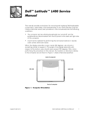
The angle of the display assembly with respect to support it. Computer Orientation support.dell.com Dell Latitude L400 Service Manual 1 Unless otherwise noted, each procedure in this manual, the locations or directions relative to the computer are disconnected from the I/O panel on the back and right side of computer Figure 1. Also, when performing ...
The angle of the display assembly with respect to support it. Computer Orientation support.dell.com Dell Latitude L400 Service Manual 1 Unless otherwise noted, each procedure in this manual, the locations or directions relative to the computer are disconnected from the I/O panel on the back and right side of computer Figure 1. Also, when performing ...
Service Manual
Page 6
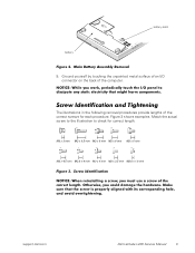
...: Make sure that the computer is docked in the L400 Advanced Port Replicator (APR), undock the computer. 4. Remove the power cable. 6. Recommended Tools Most of the procedures in this manual require the use of one or more of the battery bay (see Figure 2). 2 Dell Latitude L400 Service Manual Turn off and not in suspend-todisk mode...
...: Make sure that the computer is docked in the L400 Advanced Port Replicator (APR), undock the computer. 4. Remove the power cable. 6. Recommended Tools Most of the procedures in this manual require the use of one or more of the battery bay (see Figure 2). 2 Dell Latitude L400 Service Manual Turn off and not in suspend-todisk mode...
Service Manual
Page 7
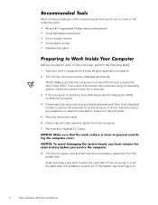
Figure 3. battery latch battery Figure 2. Main Battery Assembly Removal 9. Screw Identification NOTICE: When reinstalling a screw, you could damage the hardware. support.dell.com Dell Latitude L400 Service Manual 3 Ground yourself by touching the unpainted metal surface of the correct length. Figure 3 shows examples. Otherwise, you must use a screw of an I /O panel to check ...
Figure 3. battery latch battery Figure 2. Main Battery Assembly Removal 9. Screw Identification NOTICE: When reinstalling a screw, you could damage the hardware. support.dell.com Dell Latitude L400 Service Manual 3 Ground yourself by touching the unpainted metal surface of the correct length. Figure 3 shows examples. Otherwise, you must use a screw of an I /O panel to check ...
Service Manual
Page 8
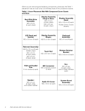
Table 1. Screw Placement Mat With Component Screw Counts and Sizes Hard-Disk Drive Assembly: M3 x 3 mm (2 each ) 4 Dell Latitude L400 Service Manual When you are removing and replacing components, photocopy the Table 1 placement mat as a tool to Base: M2 x 4 mm (2 each, black) M2 x 4.5 mm (2 each, silver) Display ...
Table 1. Screw Placement Mat With Component Screw Counts and Sizes Hard-Disk Drive Assembly: M3 x 3 mm (2 each ) 4 Dell Latitude L400 Service Manual When you are removing and replacing components, photocopy the Table 1 placement mat as a tool to Base: M2 x 4 mm (2 each, black) M2 x 4.5 mm (2 each, silver) Display ...
Service Manual
Page 9
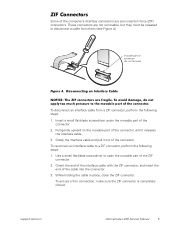
... cable with the ZIF connector, and insert the end of the ZIF connector. 2. While holding the cable in place, close the ZIF connector. support.dell.com Dell Latitude L400 Service Manual 5 Grasp the interface cable and pull it releases the interface cable. 3. To avoid damage, do not remove) Figure 4. These connectors are not removable, but...
... cable with the ZIF connector, and insert the end of the ZIF connector. 2. While holding the cable in place, close the ZIF connector. support.dell.com Dell Latitude L400 Service Manual 5 Grasp the interface cable and pull it releases the interface cable. 3. To avoid damage, do not remove) Figure 4. These connectors are not removable, but...
Service Manual
Page 10
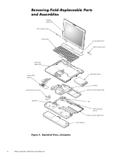
Exploded View-Computer 6 Dell Latitude L400 Service Manual Removing Field-Replaceable Parts and Assemblies display assembly left hinge cover keyboard keyboard bezel right hinge cover palmrest assembly audio EMI shield audio I/O port cover speaker hard-disk drive modem system board assembly fan APR docking doors bottom case assembly main battery Figure 5.
Exploded View-Computer 6 Dell Latitude L400 Service Manual Removing Field-Replaceable Parts and Assemblies display assembly left hinge cover keyboard keyboard bezel right hinge cover palmrest assembly audio EMI shield audio I/O port cover speaker hard-disk drive modem system board assembly fan APR docking doors bottom case assembly main battery Figure 5.
Service Manual
Page 11
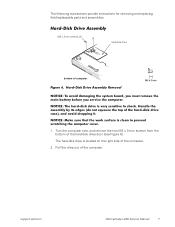
.... 2. Hard-Disk Drive Assembly Removal NOTICE: To avoid damaging the system board, you must remove the main battery before you service the computer. support.dell.com Dell Latitude L400 Service Manual 7 The hard-disk drive is located on the right side of the computer. NOTICE: Make sure that the work surface is very sensitive to...
.... 2. Hard-Disk Drive Assembly Removal NOTICE: To avoid damaging the system board, you must remove the main battery before you service the computer. support.dell.com Dell Latitude L400 Service Manual 7 The hard-disk drive is located on the right side of the computer. NOTICE: Make sure that the work surface is very sensitive to...
Service Manual
Page 12
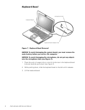
While pushing down (see Figure 7). 1. Lift the keyboard bezel. 8 Dell Latitude L400 Service Manual Keyboard Bezel Removal NOTICE: To avoid damaging the system board, you must remove the main battery before you service the computer. Place the point of a ...
While pushing down (see Figure 7). 1. Lift the keyboard bezel. 8 Dell Latitude L400 Service Manual Keyboard Bezel Removal NOTICE: To avoid damaging the system board, you must remove the main battery before you service the computer. Place the point of a ...
Service Manual
Page 13
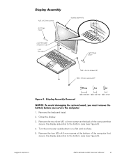
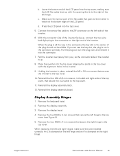
.... 5. Remove the two M2 x 4.5-mm screws at the back of the computer that secure the display assembly to the bottom case (see Figure 8). 4. support.dell.com Dell Latitude L400 Service Manual 9 Remove the two silver M2 x 4-mm screws at the bottom of the computer that secure the display assembly to the bottom case (see Figure...
.... 5. Remove the two M2 x 4.5-mm screws at the back of the computer that secure the display assembly to the bottom case (see Figure 8). 4. support.dell.com Dell Latitude L400 Service Manual 9 Remove the two silver M2 x 4-mm screws at the bottom of the computer that secure the display assembly to the bottom case (see Figure...
Service Manual
Page 14
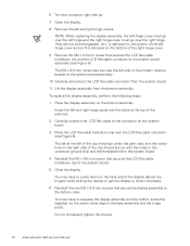
... flex-cable connector (see Figure 8). Carefully connect the LCD flex cable to the bottom case. Close the display. Do not completely tighten the screws. 10 Dell Latitude L400 Service Manual Remove the left hinge cover and an R is stamped on the bottom of the right hinge cover. 9. The M2 x 9.5-mm screw also secures the...
... flex-cable connector (see Figure 8). Carefully connect the LCD flex cable to the bottom case. Close the display. Do not completely tighten the screws. 10 Dell Latitude L400 Service Manual Remove the left hinge cover and an R is stamped on the bottom of the right hinge cover. 9. The M2 x 9.5-mm screw also secures the...
Service Manual
Page 15
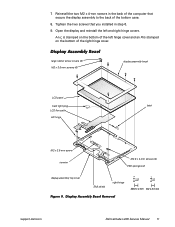
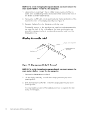
... on the bottom of the left hinge cover and an R is stamped on the bottom of the bottom case. 8. Display Assembly Bezel Removal support.dell.com Dell Latitude L400 Service Manual 11 Open the display and reinstall the left hinge latch M2 x 3.5-mm screw inverter M2.6 x 4-mm screws (4) EMI sponges (2) display-assembly top cover EMI...
... on the bottom of the left hinge cover and an R is stamped on the bottom of the bottom case. 8. Display Assembly Bezel Removal support.dell.com Dell Latitude L400 Service Manual 11 Open the display and reinstall the left hinge latch M2 x 3.5-mm screw inverter M2.6 x 4-mm screws (4) EMI sponges (2) display-assembly top cover EMI...
Service Manual
Page 16
... bottom of the bezel on the front of the display assembly (see Figure 9). 3. Use a scribe to separate the latch spring from the post. 12 Dell Latitude L400 Service Manual Remove the six M2 x 3.5-mm screws located at the top and bottom of the bezel on the front of the display assembly (see Figure 9). 2. Lift...
... bottom of the bezel on the front of the display assembly (see Figure 9). 3. Use a scribe to separate the latch spring from the post. 12 Dell Latitude L400 Service Manual Remove the six M2 x 3.5-mm screws located at the top and bottom of the bezel on the front of the display assembly (see Figure 9). 2. Lift...
Service Manual
Page 17
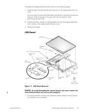
... following steps: 1. Holding the latch, stretch the spring slightly and set the display-assembly latch in place in the display assembly top cover. 3. support.dell.com Dell Latitude L400 Service Manual 13 Carefully place the latch spring over the post. You may need to use a small flat-blade screwdriver to place the spring over the...
... following steps: 1. Holding the latch, stretch the spring slightly and set the display-assembly latch in place in the display assembly top cover. 3. support.dell.com Dell Latitude L400 Service Manual 13 Carefully place the latch spring over the post. You may need to use a small flat-blade screwdriver to place the spring over the...
Service Manual
Page 18
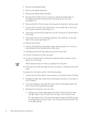
... press against the back of the LCD panel, insert the right edge of the LCD panel into the right end of the EMI sponge. 14 Dell Latitude L400 Service Manual Remove the four M2 x 3.5-mm screws on the LCD flex-cable EMI sponges. 4. Connect the LCD flex cable to fit your hand between the...
... press against the back of the LCD panel, insert the right edge of the LCD panel into the right end of the EMI sponge. 14 Dell Latitude L400 Service Manual Remove the four M2 x 3.5-mm screws on the LCD flex-cable EMI sponges. 4. Connect the LCD flex cable to fit your hand between the...
Service Manual
Page 19
... into the top cover, aligning the posts in the top cover with the opening that secures the inverter to the inverter is up. 8. support.dell.com Dell Latitude L400 Service Manual 15 b. Lower the bottom end of the inverter. 6. Connect the narrow flex cable to the top cover. With the connector side of the inverter...
... into the top cover, aligning the posts in the top cover with the opening that secures the inverter to the inverter is up. 8. support.dell.com Dell Latitude L400 Service Manual 15 b. Lower the bottom end of the inverter. 6. Connect the narrow flex cable to the top cover. With the connector side of the inverter...
Service Manual
Page 20
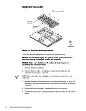
... x 4-mm screws located across the top of the keyboard in the palmrest assembly. 3. Release the keyboard assembly from the connector on the system board. 16 Dell Latitude L400 Service Manual Remove the keyboard bezel. 2. NOTICE: To avoid damaging the system board, you must remove the main battery before you service the computer. Rotate the...
... x 4-mm screws located across the top of the keyboard in the palmrest assembly. 3. Release the keyboard assembly from the connector on the system board. 16 Dell Latitude L400 Service Manual Remove the keyboard bezel. 2. NOTICE: To avoid damaging the system board, you must remove the main battery before you service the computer. Rotate the...
Service Manual
Page 21
... look through the hard-disk drive bay to make sure the tabs are fragile, easily dislodged, and time-consuming to the bottom assembly. 6. support.dell.com Dell Latitude L400 Service Manual 17 When the keyboard assembly is important that the top screw-hole tabs rest correctly in the screw slots on the palmrest assembly. 4. Verify...
... look through the hard-disk drive bay to make sure the tabs are fragile, easily dislodged, and time-consuming to the bottom assembly. 6. support.dell.com Dell Latitude L400 Service Manual 17 When the keyboard assembly is important that the top screw-hole tabs rest correctly in the screw slots on the palmrest assembly. 4. Verify...
Service Manual
Page 22
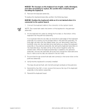
... the socket in the center of the memory module socket just far enough for the memory module to fit into the memory module socket. 18 Dell Latitude L400 Service Manual The memory module is notched so that the memory module can be firmly seated only one direction. Remove the keyboard assembly. 3. The slot on...
... the socket in the center of the memory module socket just far enough for the memory module to fit into the memory module socket. 18 Dell Latitude L400 Service Manual The memory module is notched so that the memory module can be firmly seated only one direction. Remove the keyboard assembly. 3. The slot on...
Service Manual
Page 23
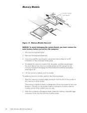
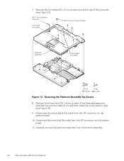
... clicks into the tabs, remove the memory module and reinstall it (see Figure 14). If you service the computer. 1. Remove the keyboard assembly. 4. support.dell.com Dell Latitude L400 Service Manual 19 3. Removing the Palmrest Assembly Bottom Screws The palmrest assembly consists of the memory module snaps into place. NOTICE: Make sure that the work...
... clicks into the tabs, remove the memory module and reinstall it (see Figure 14). If you service the computer. 1. Remove the keyboard assembly. 4. support.dell.com Dell Latitude L400 Service Manual 19 3. Removing the Palmrest Assembly Bottom Screws The palmrest assembly consists of the memory module snaps into place. NOTICE: Make sure that the work...
Service Manual
Page 24
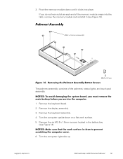
... 8. Carefully remove the palmrest assembly from the ZIF connector on the system board. 11. Disconnect the status lights flex cable from the bottom assembly. 20 Dell Latitude L400 Service Manual Disconnect the touch pad flex cable from the ZIF connector on the system board. 10. Remove the four black M2 x 4-mm screws across the...
... 8. Carefully remove the palmrest assembly from the ZIF connector on the system board. 11. Disconnect the status lights flex cable from the bottom assembly. 20 Dell Latitude L400 Service Manual Disconnect the touch pad flex cable from the ZIF connector on the system board. 10. Remove the four black M2 x 4-mm screws across the...


