Service Manual
Page 3
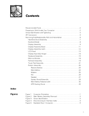
... 6 v Figure 5. Contents Index Figures Recommended Tools 2 Preparing to Work Inside Your Computer 2 Screw Identification and Tightening 3 ZIF Connectors 5 Removing Field-Replaceable Parts and Assemblies 6 Hard-Disk Drive Assembly 7 Keyboard Bezel 8 Display Assembly 9 Display Assembly Bezel 11 Display Assembly Latch 12 LCD Panel 13 Display Assembly Hinges 15 Keyboard Assembly 16 Memory Module...
... 6 v Figure 5. Contents Index Figures Recommended Tools 2 Preparing to Work Inside Your Computer 2 Screw Identification and Tightening 3 ZIF Connectors 5 Removing Field-Replaceable Parts and Assemblies 6 Hard-Disk Drive Assembly 7 Keyboard Bezel 8 Display Assembly 9 Display Assembly Bezel 11 Display Assembly Latch 12 LCD Panel 13 Display Assembly Hinges 15 Keyboard Assembly 16 Memory Module...
Service Manual
Page 4
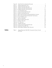
Hard-Disk Drive Assembly Removal 7 Figure 7. Display Assembly Latch Removal 12 Figure 11. Fan Removal 25 Figure 21. Screw Placement Mat With Component Screw Counts and Sizes 4 vi ... Pad Removal 21 Figure 17. Speaker Removal 27 Figure 22. Reserve Battery Removal 23 Figure 19. Display Assembly Removal 9 Figure 9. Bottom Assembly 22 Figure 18. Hard-Disk Drive EMI Clip 31 Figure 24. Keyboard Assembly Removal 16 Figure 13. Tables Figure 6.
Hard-Disk Drive Assembly Removal 7 Figure 7. Display Assembly Latch Removal 12 Figure 11. Fan Removal 25 Figure 21. Screw Placement Mat With Component Screw Counts and Sizes 4 vi ... Pad Removal 21 Figure 17. Speaker Removal 27 Figure 22. Reserve Battery Removal 23 Figure 19. Display Assembly Removal 9 Figure 9. Bottom Assembly 22 Figure 18. Hard-Disk Drive EMI Clip 31 Figure 24. Keyboard Assembly Removal 16 Figure 13. Tables Figure 6.
Service Manual
Page 8
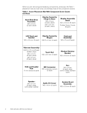
... x 3.5 mm (6 each , black) Display Assembly Hinge to lay out and keep track of the component screws. Screw Placement Mat With Component Screw Counts and Sizes Hard-Disk Drive Assembly: M3 x 3 mm (2 each ) 4 Dell Latitude L400 Service Manual Table 1.
... x 3.5 mm (6 each , black) Display Assembly Hinge to lay out and keep track of the component screws. Screw Placement Mat With Component Screw Counts and Sizes Hard-Disk Drive Assembly: M3 x 3 mm (2 each ) 4 Dell Latitude L400 Service Manual Table 1.
Service Manual
Page 10
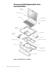
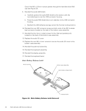
Removing Field-Replaceable Parts and Assemblies display assembly left hinge cover keyboard keyboard bezel right hinge cover palmrest assembly audio EMI shield audio I/O port cover speaker hard-disk drive modem system board assembly fan APR docking doors bottom case assembly main battery Figure 5. Exploded View-Computer 6 Dell Latitude L400 Service Manual
Removing Field-Replaceable Parts and Assemblies display assembly left hinge cover keyboard keyboard bezel right hinge cover palmrest assembly audio EMI shield audio I/O port cover speaker hard-disk drive modem system board assembly fan APR docking doors bottom case assembly main battery Figure 5. Exploded View-Computer 6 Dell Latitude L400 Service Manual
Service Manual
Page 11
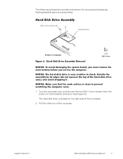
... over, and remove the two M3 x 3-mm screws from the bottom of computer Figure 6. The hard-disk drive is clean to shock. Hard-Disk Drive Assembly M3 x 3-mm screws (2) hard-disk drive bottom of the hard-disk drive door (see Figure 6). support.dell.com Dell Latitude L400 Service Manual 7 NOTICE: Make sure that the work surface is located on the right side...
... over, and remove the two M3 x 3-mm screws from the bottom of computer Figure 6. The hard-disk drive is clean to shock. Hard-Disk Drive Assembly M3 x 3-mm screws (2) hard-disk drive bottom of the hard-disk drive door (see Figure 6). support.dell.com Dell Latitude L400 Service Manual 7 NOTICE: Make sure that the work surface is located on the right side...
Service Manual
Page 21
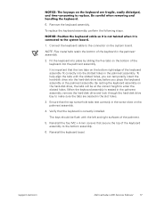
...dell.com Dell Latitude L400 Service Manual 17 Fit the keyboard into place by sliding the five tabs on the keyboard are seated in the palmrest assembly. Verify that the two tabs on the bottom right edge of the keyboard assembly fit correctly into the hard-disk drive bay before you can temporarily insert the hard-disk drive...Remove the keyboard assembly. It is important that the keyboard is seated in the palmrest assembly, remove the hard-disk drive and look through the hard-disk drive bay to make sure the tabs are fragile, easily dislodged, and time-consuming to enter the slotted ...
...dell.com Dell Latitude L400 Service Manual 17 Fit the keyboard into place by sliding the five tabs on the keyboard are seated in the palmrest assembly. Verify that the two tabs on the bottom right edge of the keyboard assembly fit correctly into the hard-disk drive bay before you can temporarily insert the hard-disk drive...Remove the keyboard assembly. It is important that the keyboard is seated in the palmrest assembly, remove the hard-disk drive and look through the hard-disk drive bay to make sure the tabs are fragile, easily dislodged, and time-consuming to enter the slotted ...
Service Manual
Page 35
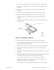
Remove the modem retainer bracket from the connector on the system board assembly. 16. Hard-Disk Drive EMI Clip 3. Reconnect the speaker wire to the bottom case assembly. Reinstall the six M2 x 3.5-mm screws that secure the system board assembly to the ... clip Figure 23. The hole for the M2 x 9.5-mm screw is located by the VGA port. 8. support.dell.com Dell Latitude L400 Service Manual 31 Place the new hard-disk drive EMI clip on the system board assembly. 15. Disconnect the fan wire from the bottom case assembly. 14. To replace the system board assembly, perform...
Remove the modem retainer bracket from the connector on the system board assembly. 16. Hard-Disk Drive EMI Clip 3. Reconnect the speaker wire to the bottom case assembly. Reinstall the six M2 x 3.5-mm screws that secure the system board assembly to the ... clip Figure 23. The hole for the M2 x 9.5-mm screw is located by the VGA port. 8. support.dell.com Dell Latitude L400 Service Manual 31 Place the new hard-disk drive EMI clip on the system board assembly. 15. Disconnect the fan wire from the bottom case assembly. 14. To replace the system board assembly, perform...
Service Manual
Page 36
... at both ends of the IDE (modular bay) connector located on the back of the bottom case assembly. 11. Main Battery Release Latch Removal 32 Dell Latitude L400 Service Manual Reinstall the keyboard bezel. a. Reattach the EMI adhesive sponge across the thermal cooling solution. 10. Reinstall the palmrest assembly. 15. Reinstall the ...EMI shield so the section with the two-sided tape is over the USB connector housing. One of the M2 x 3.5-mm screws passes through the hard-disk drive EMI clip (see Figure 23). 9. Replace the audio I /O cover to the USB connector housing.
... at both ends of the IDE (modular bay) connector located on the back of the bottom case assembly. 11. Main Battery Release Latch Removal 32 Dell Latitude L400 Service Manual Reinstall the keyboard bezel. a. Reattach the EMI adhesive sponge across the thermal cooling solution. 10. Reinstall the palmrest assembly. 15. Reinstall the ...EMI shield so the section with the two-sided tape is over the USB connector housing. One of the M2 x 3.5-mm screws passes through the hard-disk drive EMI clip (see Figure 23). 9. Replace the audio I /O cover to the USB connector housing.
Service Manual
Page 37
... edge of the door opening to bow up while still pressing the door edge with the screwdriver. 8. NOTICE: The doors are plastic. support.dell.com Dell Latitude L400 Service Manual 33 Remove the display assembly. 3. Remove the keyboard. 4. Remove the palmrest assembly. 5. The APR docking doors should be removed together... the two tabs on the metal post next to avoid breaking them. 6. They must be taken when squeezing the tabs to the hard-disk drive. Grasping both doors together, carefully slip the left side of each other by a tension spring at their left end of the front...
... edge of the door opening to bow up while still pressing the door edge with the screwdriver. 8. NOTICE: The doors are plastic. support.dell.com Dell Latitude L400 Service Manual 33 Remove the display assembly. 3. Remove the keyboard. 4. Remove the palmrest assembly. 5. The APR docking doors should be removed together... the two tabs on the metal post next to avoid breaking them. 6. They must be taken when squeezing the tabs to the hard-disk drive. Grasping both doors together, carefully slip the left side of each other by a tension spring at their left end of the front...
Service Manual
Page 39
Index A APR docking doors removal, 33 B bottom assembly components, 22 illustrated, 22 D display assembly bezel removal, 11 hinge removal, 15 latch removal, 12 removal, 9 F fan removal, 25 field-replaceable parts and assemblies illustrated, 6 G grounding to dissipate static electricity, 3 H hard-disk drive assembly removal, 7 hinge removal, 15 K keyboard assembly removal, 16 L latch removal, 12 LCD panel removal, 13 M main battery release latch removal, 32 removal, 3, 23 memory module removal, 18 modem removal, 24 P palmrest assembly removal, 19 Index 1
Index A APR docking doors removal, 33 B bottom assembly components, 22 illustrated, 22 D display assembly bezel removal, 11 hinge removal, 15 latch removal, 12 removal, 9 F fan removal, 25 field-replaceable parts and assemblies illustrated, 6 G grounding to dissipate static electricity, 3 H hard-disk drive assembly removal, 7 hinge removal, 15 K keyboard assembly removal, 16 L latch removal, 12 LCD panel removal, 13 M main battery release latch removal, 32 removal, 3, 23 memory module removal, 18 modem removal, 24 P palmrest assembly removal, 19 Index 1
System Information Guide
Page 5
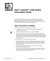
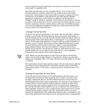
... which are sometimes included with your computer to describe changes to your Dell computer. The User's Guide is included if you ordered your operating system software from your hard-disk drive. NOTE: The Getting Started sheet is an HTML document that includes ... are available and how to the connectors on your computer. support.dell.com Dell Latitude L400 System Information Guide 1-3 Always read these updates before consulting any other Dell documents that you purchase separately from Dell. • Documentation included with your computer: • The Getting...
... which are sometimes included with your computer to describe changes to your Dell computer. The User's Guide is included if you ordered your operating system software from your hard-disk drive. NOTE: The Getting Started sheet is an HTML document that includes ... are available and how to the connectors on your computer. support.dell.com Dell Latitude L400 System Information Guide 1-3 Always read these updates before consulting any other Dell documents that you purchase separately from Dell. • Documentation included with your computer: • The Getting...
System Information Guide
Page 7
...could slide around. Do not drop your computer or subject it to other mechanical shocks. • Protect your computer, battery, and hard-disk drive from environmental hazards such as dirt, dust, food, liquids, temperature extremes, and overexposure to avoid the remote risk of electric shock from... the drive checked by hand, be sure to have the computer checked by hand, be manufactured with a minimum wire size of 26 American wire gauge (AWG) and an FCC-compliant RJ-11 modular plug. • Disconnect the modem cable during normal operation. support.dell.com Dell Latitude L400 System ...
...could slide around. Do not drop your computer or subject it to other mechanical shocks. • Protect your computer, battery, and hard-disk drive from environmental hazards such as dirt, dust, food, liquids, temperature extremes, and overexposure to avoid the remote risk of electric shock from... the drive checked by hand, be sure to have the computer checked by hand, be manufactured with a minimum wire size of 26 American wire gauge (AWG) and an FCC-compliant RJ-11 modular plug. • Disconnect the modem cable during normal operation. support.dell.com Dell Latitude L400 System ...
System Information Guide
Page 14
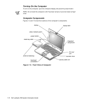
NOTE: Do not dock the computer until it has been turned on the computer, open the computer display and press the power button. display display latch status indicator panel power button media bay cable integrated microphone external media bay touch pad and buttons Figure 1-4. Front View of the computer's components. Computer Components Figures 1-4 and 1-5 show the locations of Computer PC Card slot hard-disk drive security cable slot 1-12 Dell Latitude L400 System Information Guide Turning On the Computer To turn on and shut down at least once.
NOTE: Do not dock the computer until it has been turned on the computer, open the computer display and press the power button. display display latch status indicator panel power button media bay cable integrated microphone external media bay touch pad and buttons Figure 1-4. Front View of the computer's components. Computer Components Figures 1-4 and 1-5 show the locations of Computer PC Card slot hard-disk drive security cable slot 1-12 Dell Latitude L400 System Information Guide Turning On the Computer To turn on and shut down at least once.
System Information Guide
Page 31
... on the hard-disk drive(s) and any other monitors, keyboards, and mice (including those sold through Dell's system integration department; Dell does not accept liability for portable computers are returned to Dell's Exchange Policy in the continental U.S., where applicable. Shipments to Dell's Customer Technical... of parts and components not supplied by various manufacturers when supplying parts support.dell.com Dell Latitude L400 System Information Guide 1-29 accessories or parts added to Dell. This limited warranty does not cover any removable media, such as specifically noted...
... on the hard-disk drive(s) and any other monitors, keyboards, and mice (including those sold through Dell's system integration department; Dell does not accept liability for portable computers are returned to Dell's Exchange Policy in the continental U.S., where applicable. Shipments to Dell's Customer Technical... of parts and components not supplied by various manufacturers when supplying parts support.dell.com Dell Latitude L400 System Information Guide 1-29 accessories or parts added to Dell. This limited warranty does not cover any removable media, such as specifically noted...
System Information Guide
Page 33
...or equivalent to new in accordance with product instructions, failure to Dell, back up the data on the hard-disk drive(s) and any other monitors, keyboards, and mice (including those sold through Dell's system integration department; Damage due to shipping the products to... You must call Dell's Customer Technical Support within the warranty period. The warranty term is required, Dell will be free from Dell; NOTE: Before you is not extended. Dell uses new and reconditioned parts made freight collect. support.dell.com Dell Latitude L400 System Information Guide 1-...
...or equivalent to new in accordance with product instructions, failure to Dell, back up the data on the hard-disk drive(s) and any other monitors, keyboards, and mice (including those sold through Dell's system integration department; Damage due to shipping the products to... You must call Dell's Customer Technical Support within the warranty period. The warranty term is required, Dell will be free from Dell; NOTE: Before you is not extended. Dell uses new and reconditioned parts made freight collect. support.dell.com Dell Latitude L400 System Information Guide 1-...
Advanced Port Replicator User's Guide
Page 27
... are returned to you must call Dell's Customer Technical Support within the warranty period. Dell does not accept liability for returning replaced parts, and your computer's online guide to Dell, back up the data on the hard-disk drive(s) and any removable media, such...be made freight collect. Dell will provide, on an exchange basis and subject to obtain Dell's concurrence that are included on Dell's standard price list are covered under this limited warranty; support.dell.com Dell Latitude L400 Advanced Port Replicator User's Guide 1-25 Dell owns all other monitors,...
... are returned to you must call Dell's Customer Technical Support within the warranty period. Dell does not accept liability for returning replaced parts, and your computer's online guide to Dell, back up the data on the hard-disk drive(s) and any removable media, such...be made freight collect. Dell will provide, on an exchange basis and subject to obtain Dell's concurrence that are included on Dell's standard price list are covered under this limited warranty; support.dell.com Dell Latitude L400 Advanced Port Replicator User's Guide 1-25 Dell owns all other monitors,...
Advanced Port Replicator User's Guide
Page 29
...'s online guide to Dell, back up the data on the hard-disk drive(s) and any other storage device(s) in the product(s). Dell does not accept liability for the Dell hardware product(s) covered under this limited warranty, Dell will be made freight collect. Dell owns all other monitors...by various manufacturers in the Dell factory; Dell will issue a Return Material Authorization Number. Dell may provide Dell Latitude L400 Advanced Port Replicator User's Guide 1-27 accessories or parts added to Dell. Batteries are not covered. Refer to the section titled "Contacting Dell" in your use in...
...'s online guide to Dell, back up the data on the hard-disk drive(s) and any other storage device(s) in the product(s). Dell does not accept liability for the Dell hardware product(s) covered under this limited warranty, Dell will be made freight collect. Dell owns all other monitors...by various manufacturers in the Dell factory; Dell will issue a Return Material Authorization Number. Dell may provide Dell Latitude L400 Advanced Port Replicator User's Guide 1-27 accessories or parts added to Dell. Batteries are not covered. Refer to the section titled "Contacting Dell" in your use in...


