
Dell Latitude E5440/E5540 Setup And Features Information
Page 6
... to Specifications' section in your Windows operating system and select the option to view information about the configuration of your computer at dell.com/support. Power AC Adapter Input voltage Coin-cell battery 65W and 90W 100 VAC to ship with 2 GB or greater graphics ...and system memory. Significant system memory may vary by law to 240 VAC 3 V CR2032 lithium ion Physical Height (E5440) Height (E5540) Width E5440 E5540 Depth E5440 E5540 Weight (minimum) E5440 E5540 Touch Front - 27.70 mm (1.09 inches) Back - 32.20 ...
... to Specifications' section in your Windows operating system and select the option to view information about the configuration of your computer at dell.com/support. Power AC Adapter Input voltage Coin-cell battery 65W and 90W 100 VAC to ship with 2 GB or greater graphics ...and system memory. Significant system memory may vary by law to 240 VAC 3 V CR2032 lithium ion Physical Height (E5440) Height (E5540) Width E5440 E5540 Depth E5440 E5540 Weight (minimum) E5440 E5540 Touch Front - 27.70 mm (1.09 inches) Back - 32.20 ...

Dell Owners Manual
Page 3
... Keyboard Trim...15 Removing the Keyboard...15 Installing the Keyboard...16 Removing the Base Cover...17 Installing the Base Cover...17 Removing the Memory Module...17 Installing the Memory Module...18 Removing the Hard Drive...18 Installing the Hard Drive...19 Removing the Hard-Drive Cage...19 Installing the Hard-Drive Cage...
... Keyboard Trim...15 Removing the Keyboard...15 Installing the Keyboard...16 Removing the Base Cover...17 Installing the Base Cover...17 Removing the Memory Module...17 Installing the Memory Module...18 Removing the Hard Drive...18 Installing the Hard Drive...19 Removing the Hard-Drive Cage...19 Installing the Hard-Drive Cage...

Dell Owners Manual
Page 9
Back 1. optical drive 4. hard drive 9 2 Removing and Installing Components This section provides detailed information on how to remove or install the components from your computer. coin-cell battery 2. memory modules 3. Recommended Tools The procedures in this document may require the following tools: • Small flat-blade screwdriver • #0 Phillips screwdriver • #1 Phillips screwdriver • Small plastic scribe System Overview Figure 1. Inside View - WLAN card 5.
Back 1. optical drive 4. hard drive 9 2 Removing and Installing Components This section provides detailed information on how to remove or install the components from your computer. coin-cell battery 2. memory modules 3. Recommended Tools The procedures in this document may require the following tools: • Small flat-blade screwdriver • #0 Phillips screwdriver • #1 Phillips screwdriver • Small plastic scribe System Overview Figure 1. Inside View - WLAN card 5.

Dell Owners Manual
Page 17
.... 2. Remove: a) battery b) base cover 3. Remove the battery. 3. b) Slide the base cover towards the front of the system and remove it from the computer. Removing the Memory Module 1. Lift up . 4. Removing the Base Cover 1. Perform the following steps: a) Remove the screws that secure the base cover to the computer. 3. Install the screws... Your Computer. 2. Installing the Base Cover 1. Install the battery. 4. Follow the procedures in After Working Inside Your Computer. Pry the retention clips away from the memory module until it clicks into its slot until it pops up the...
.... 2. Remove: a) battery b) base cover 3. Remove the battery. 3. b) Slide the base cover towards the front of the system and remove it from the computer. Removing the Memory Module 1. Lift up . 4. Removing the Base Cover 1. Perform the following steps: a) Remove the screws that secure the base cover to the computer. 3. Install the screws... Your Computer. 2. Installing the Base Cover 1. Install the battery. 4. Follow the procedures in After Working Inside Your Computer. Pry the retention clips away from the memory module until it clicks into its slot until it pops up the...

Dell Owners Manual
Page 18
Follow the procedures in Before Working Inside Your Computer. 2. b) Remove the hard-drive bracket from its connectors. 4. Insert the memory into the memory socket. 2. Removing the Hard Drive 1. Follow the procedures in After Working Inside Your Computer. b) Pull the hard drive to the system board. 3. Install: a) base cover b).... After removing the hard drive, perform the following steps: a) Remove the screws that secure the hard-drive bracket. Press the clips to secure the memory module to remove from the hard drive. 18 Remove: a) battery b) base cover 3. Installing the...
Follow the procedures in Before Working Inside Your Computer. 2. b) Remove the hard-drive bracket from its connectors. 4. Insert the memory into the memory socket. 2. Removing the Hard Drive 1. Follow the procedures in After Working Inside Your Computer. b) Pull the hard drive to the system board. 3. Install: a) base cover b).... After removing the hard drive, perform the following steps: a) Remove the screws that secure the hard-drive bracket. Press the clips to secure the memory module to remove from the hard drive. 18 Remove: a) battery b) base cover 3. Installing the...

Dell Owners Manual
Page 23
... Display Hinge 1. Place the display hinge on the computer. 2. Install: a) keyboard b) keyboard trim c) base cover d) battery 4. Remove: a) SD card b) battery c) base cover d) keyboard trim e) keyboard f) memory g) optical drive h) hard drive i) hard-drive cage j) display hinge 3.
... Display Hinge 1. Place the display hinge on the computer. 2. Install: a) keyboard b) keyboard trim c) base cover d) battery 4. Remove: a) SD card b) battery c) base cover d) keyboard trim e) keyboard f) memory g) optical drive h) hard drive i) hard-drive cage j) display hinge 3.
Dell Owners Manual
Page 24
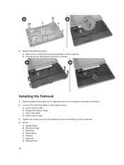
... cable d) media button cable 3. Installing the Palmrest 1. b) Lift and remove the palmrest from the computer. Install: a) display hinge b) hard-drive cage c) hard drive d) optical drive e) memory f) keyboard g) keyboard trim 24 Align the palmrest assembly to secure the palmrest at the front and back of the computer. 4. Connect the following steps: a) Remove...
... cable d) media button cable 3. Installing the Palmrest 1. b) Lift and remove the palmrest from the computer. Install: a) display hinge b) hard-drive cage c) hard drive d) optical drive e) memory f) keyboard g) keyboard trim 24 Align the palmrest assembly to secure the palmrest at the front and back of the computer. 4. Connect the following steps: a) Remove...

Dell Owners Manual
Page 26
Follow the procedures in After Working Inside Your Computer. Remove: a) SD card b) battery c) base cover d) keyboard trim e) keyboard f) memory g) optical drive h) hard drive i) hard-drive cage j) display hinge k) palmrest 3. Tighten the screws to remove the system fan from the computer. Removing the ... procedures in Before Working Inside Your Computer. 2. Perform the following steps: a) Disconnect the I /O board cable to the system board. 3. Install: a) palmrest b) display hinge c) memory d) hard-drive cage e) hard drive 26 Connect the system-fan cable to its connector. 4.
Follow the procedures in After Working Inside Your Computer. Remove: a) SD card b) battery c) base cover d) keyboard trim e) keyboard f) memory g) optical drive h) hard drive i) hard-drive cage j) display hinge k) palmrest 3. Tighten the screws to remove the system fan from the computer. Removing the ... procedures in Before Working Inside Your Computer. 2. Perform the following steps: a) Disconnect the I /O board cable to the system board. 3. Install: a) palmrest b) display hinge c) memory d) hard-drive cage e) hard drive 26 Connect the system-fan cable to its connector. 4.

Dell Owners Manual
Page 27
f) optical drive g) keyboard h) keyboard trim i) base cover j) battery k) SD card 6. Follow the procedures in Before Working Inside Your Computer. 2. Disconnect: a) coin-cell battery cable b) power-connector cable c) speaker cable 27 Removing the System Board 1. Follow the procedures in After Working Inside Your Computer. Remove: a) SD card b) battery c) base cover d) keyboard trim e) keyboard f) memory g) optical drive h) hard drive i) hard-drive cage j) WLAN card k) display hinge l) palmrest m) system fan n) ExpressCard cage 3.
f) optical drive g) keyboard h) keyboard trim i) base cover j) battery k) SD card 6. Follow the procedures in Before Working Inside Your Computer. 2. Disconnect: a) coin-cell battery cable b) power-connector cable c) speaker cable 27 Removing the System Board 1. Follow the procedures in After Working Inside Your Computer. Remove: a) SD card b) battery c) base cover d) keyboard trim e) keyboard f) memory g) optical drive h) hard drive i) hard-drive cage j) WLAN card k) display hinge l) palmrest m) system fan n) ExpressCard cage 3.

Dell Owners Manual
Page 29
Remove: a) SD card b) battery c) base cover d) keyboard trim e) keyboard f) memory g) optical drive h) hard drive i) hard-drive cage j) WLAN card k) display hinge l) palmrest m) system fan n) ExpressCard cage o) system board 3. Perform the following steps: a) ... b) Lift to remove the heatsink from the computer. 29 b) system fan c) palmrest d) display hinge e) WLAN card f) hard-drive cage g) hard drive h) optical drive i) memory j) keyboard k) keyboard trim l) base cover m) battery n) SD card 6. Removing the Heatsink 1. Follow the procedures in After Working Inside Your Computer.
Remove: a) SD card b) battery c) base cover d) keyboard trim e) keyboard f) memory g) optical drive h) hard drive i) hard-drive cage j) WLAN card k) display hinge l) palmrest m) system fan n) ExpressCard cage o) system board 3. Perform the following steps: a) ... b) Lift to remove the heatsink from the computer. 29 b) system fan c) palmrest d) display hinge e) WLAN card f) hard-drive cage g) hard drive h) optical drive i) memory j) keyboard k) keyboard trim l) base cover m) battery n) SD card 6. Removing the Heatsink 1. Follow the procedures in After Working Inside Your Computer.

Dell Owners Manual
Page 30
Remove: a) SD card b) battery c) base cover 30 Follow the procedures in Before Working Inside Your Computer. 2. Place the heatsink on the system board. 2. Tighten the screws to secure the heatsink to the computer. 3. Install: a) system board b) ExpressCard cage c) system fan d) palmrest e) display hinge f) WLAN card g) hard-drive cage h) hard drive i) optical drive j) memory k) keyboard l) keyboard trim m) base cover n) battery o) SD card 4. Follow the procedures in After Working Inside Your Computer. Installing the Heatsink 1. Removing the I/O Board (Left) 1.
Remove: a) SD card b) battery c) base cover 30 Follow the procedures in Before Working Inside Your Computer. 2. Place the heatsink on the system board. 2. Tighten the screws to secure the heatsink to the computer. 3. Install: a) system board b) ExpressCard cage c) system fan d) palmrest e) display hinge f) WLAN card g) hard-drive cage h) hard drive i) optical drive j) memory k) keyboard l) keyboard trim m) base cover n) battery o) SD card 4. Follow the procedures in After Working Inside Your Computer. Installing the Heatsink 1. Removing the I/O Board (Left) 1.

Dell Owners Manual
Page 31
...3. Install: a) system board b) ExpressCard cage c) system fan d) palmrest e) display hinge f) WLAN card g) hard-drive cage h) hard drive i) optical drive j) memory k) keyboard l) keyboard trim m) base cover n) battery 31 Place the I/O board on the computer. Perform the following steps: a) Remove the screw that secures the ...board and remove from the computer. b) Lift the I /O board on the computer. 2. d) keyboard trim e) keyboard f) memory g) optical drive h) hard drive i) hard-drive cage j) WLAN card k) display hinge l) palmrest m) system fan n) ExpressCard cage o) system board 3.
...3. Install: a) system board b) ExpressCard cage c) system fan d) palmrest e) display hinge f) WLAN card g) hard-drive cage h) hard drive i) optical drive j) memory k) keyboard l) keyboard trim m) base cover n) battery 31 Place the I/O board on the computer. Perform the following steps: a) Remove the screw that secures the ...board and remove from the computer. b) Lift the I /O board on the computer. 2. d) keyboard trim e) keyboard f) memory g) optical drive h) hard drive i) hard-drive cage j) WLAN card k) display hinge l) palmrest m) system fan n) ExpressCard cage o) system board 3.

Dell Owners Manual
Page 32
... computer. 3. Follow the procedures in Before Working Inside Your Computer. 2. Place the I /O board on the computer. 2. Remove: a) SD card b) battery c) base cover d) keyboard trim e) keyboard f) memory g) optical drive h) hard drive i) hard-drive cage j) WLAN card k) display hinge l) palmrest m) system fan n) ExpressCard cage o) system board 3. o) SD card 4. Follow the procedures in After...
... computer. 3. Follow the procedures in Before Working Inside Your Computer. 2. Place the I /O board on the computer. 2. Remove: a) SD card b) battery c) base cover d) keyboard trim e) keyboard f) memory g) optical drive h) hard drive i) hard-drive cage j) WLAN card k) display hinge l) palmrest m) system fan n) ExpressCard cage o) system board 3. o) SD card 4. Follow the procedures in After...

Dell Owners Manual
Page 33
... l) keyboard trim m) base cover n) battery o) SD card 4. Follow the procedures in Before Working Inside Your Computer. 2. Remove: a) SD card b) battery c) base cover d) keyboard trim e) keyboard f) memory g) hard drive h) hard-drive cage i) optical drive j) WLAN card k) display hinge l) palmrest m) ExpressCard cage n) system fan o) system board 3. Perform the following steps: a) Remove the power...
... l) keyboard trim m) base cover n) battery o) SD card 4. Follow the procedures in Before Working Inside Your Computer. 2. Remove: a) SD card b) battery c) base cover d) keyboard trim e) keyboard f) memory g) hard drive h) hard-drive cage i) optical drive j) WLAN card k) display hinge l) palmrest m) ExpressCard cage n) system fan o) system board 3. Perform the following steps: a) Remove the power...

Dell Owners Manual
Page 34
...a) system board b) system fan c) ExpressCard cage d) palmrest e) display hinge f) WLAN card g) hard-drive cage h) hard drive i) optical drive j) memory k) keyboard l) keyboard trim m) base cover n) battery o) SD card 4. Removing the Speakers 1. Follow the procedures in the computer. 2. Perform the... After Working Inside Your Computer. b) Remove the screws that secure the speakers from the computer. Remove: a) SD memory card b) battery c) base cover d) keyboard trim e) keyboard f) memory g) optical drive h) hard drive i) hard-drive cage j) WLAN card k) display hinge l) palmrest m) system fan...
...a) system board b) system fan c) ExpressCard cage d) palmrest e) display hinge f) WLAN card g) hard-drive cage h) hard drive i) optical drive j) memory k) keyboard l) keyboard trim m) base cover n) battery o) SD card 4. Removing the Speakers 1. Follow the procedures in the computer. 2. Perform the... After Working Inside Your Computer. b) Remove the screws that secure the speakers from the computer. Remove: a) SD memory card b) battery c) base cover d) keyboard trim e) keyboard f) memory g) optical drive h) hard drive i) hard-drive cage j) WLAN card k) display hinge l) palmrest m) system fan...

Dell Owners Manual
Page 35
... board b) ExpressCard cage c) system fan d) palmrest e) display hinge f) WLAN card g) hard-drive cage h) hard drive i) optical drive j) memory k) keyboard l) keyboard trim m) base cover n) battery o) SD card 5. Removing the Status-Light Board 1. Tighten the screws to secure the ...channels. 3. Secure the speaker cable to the computer. 4. Remove: a) SD card b) battery c) base cover d) keyboard trim e) keyboard f) memory g) optical drive 35 Installing the Speakers 1. Follow the procedures in Before Working Inside Your Computer. 2. Follow the procedures in After Working Inside Your ...
... board b) ExpressCard cage c) system fan d) palmrest e) display hinge f) WLAN card g) hard-drive cage h) hard drive i) optical drive j) memory k) keyboard l) keyboard trim m) base cover n) battery o) SD card 5. Removing the Status-Light Board 1. Tighten the screws to secure the ...channels. 3. Secure the speaker cable to the computer. 4. Remove: a) SD card b) battery c) base cover d) keyboard trim e) keyboard f) memory g) optical drive 35 Installing the Speakers 1. Follow the procedures in Before Working Inside Your Computer. 2. Follow the procedures in After Working Inside Your ...

Dell Owners Manual
Page 37
a) speakers b) system board c) system fan d) ExpressCard cage e) palmrest f) display hinge g) WLAN card h) hard-drive cage i) hard drive j) optical drive k) memory l) keyboard m) keyboard trim n) base cover o) battery p) SD card 6. Follow the procedures in After Working Inside Your Computer. 37
a) speakers b) system board c) system fan d) ExpressCard cage e) palmrest f) display hinge g) WLAN card h) hard-drive cage i) hard drive j) optical drive k) memory l) keyboard m) keyboard trim n) base cover o) battery p) SD card 6. Follow the procedures in After Working Inside Your Computer. 37
Dell Owners Manual
Page 40
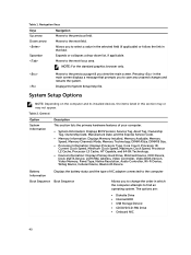
... Tag, Asset Tag, Ownership Tag, Ownership Date, Manufacture Date, and the Express Service Code. • Memory Information: Displays Memory Installed, Memory Available, Memory Speed, Memory Channels Mode, Memory Technology, DIMM ASize, DIMM B Size, • Processor Information: Displays Processor Type, Core Count, Processor ID... Primary Hard Drive, MiniCard Device, ODD Device, Dock eSATA Device, LOM MAC Address, Video Controller, Video BIOS Version, Video Memory, Panel Type, Native Resolution, Audio Controller, Wi-Fi Device, WiGig Device, Cellular Device, Bluetooth Device. The options are: ...
... Tag, Asset Tag, Ownership Tag, Ownership Date, Manufacture Date, and the Express Service Code. • Memory Information: Displays Memory Installed, Memory Available, Memory Speed, Memory Channels Mode, Memory Technology, DIMM ASize, DIMM B Size, • Processor Information: Displays Processor Type, Core Count, Processor ID... Primary Hard Drive, MiniCard Device, ODD Device, Dock eSATA Device, LOM MAC Address, Video Controller, Video BIOS Version, Video Memory, Panel Type, Native Resolution, Audio Controller, Wi-Fi Device, WiGig Device, Cellular Device, Bluetooth Device. The options are: ...
Dell Owners Manual
Page 42
... default This option, when enabled, pressing Fn+B turns of all light and sound emissions in the BIOS setup irrespective of USB Mass Storage Devices (HDD, memory key, floppy). This field enables or disables the integrated audio controller. To resume normal operation, press Fn+B again. The keyboard brightness level can be set...
... default This option, when enabled, pressing Fn+B turns of all light and sound emissions in the BIOS setup irrespective of USB Mass Storage Devices (HDD, memory key, floppy). This field enables or disables the integrated audio controller. To resume normal operation, press Fn+B again. The keyboard brightness level can be set...
Dell Owners Manual
Page 55
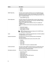
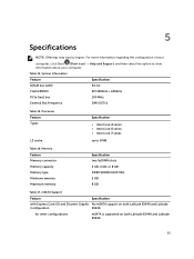
...; Help and Support, and then select the option to 8 MB Table 16. for other configurations mSATA is supported on both Latitude E5440 and Latitude E5540. 55 Memory Feature Memory connector Memory capacity Memory type Minimum memory Maximum memory Specification two SoDIMM slots 2 GB, 4 GB, or 8 GB DDR3 SDRAM 1600 Mhz 2 GB 8 GB Table 17....DMI (5GT/s) Table 15. mSATA Support Feature Specification with Express Card I/O and Discrete Graphic No mSATA support on both Latitude E5440 and Latitude Configuration E5540. 5 Specifications NOTE: Offerings may vary by region. Table 14.
...; Help and Support, and then select the option to 8 MB Table 16. for other configurations mSATA is supported on both Latitude E5440 and Latitude E5540. 55 Memory Feature Memory connector Memory capacity Memory type Minimum memory Maximum memory Specification two SoDIMM slots 2 GB, 4 GB, or 8 GB DDR3 SDRAM 1600 Mhz 2 GB 8 GB Table 17....DMI (5GT/s) Table 15. mSATA Support Feature Specification with Express Card I/O and Discrete Graphic No mSATA support on both Latitude E5440 and Latitude Configuration E5540. 5 Specifications NOTE: Offerings may vary by region. Table 14.


