Dell Latitude E5440/E5540 Setup And Features Information
Page 1
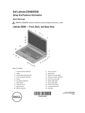
... 19. Front, Back, and Base View Figure 1. finger print reader (optional) 15. array microphone (optional) 5. optical-drive eject button 14. Latitude E5440 - battery status light 17. power button 8. power status light 18. Front View 1. Dell Latitude E5440/E5540 Setup And Features Information About Warnings WARNING: A WARNING indicates a potential for property damage, personal injury, or death.
... 19. Front, Back, and Base View Figure 1. finger print reader (optional) 15. array microphone (optional) 5. optical-drive eject button 14. Latitude E5440 - battery status light 17. power button 8. power status light 18. Front View 1. Dell Latitude E5440/E5540 Setup And Features Information About Warnings WARNING: A WARNING indicates a potential for property damage, personal injury, or death.

Dell Latitude E5440/E5540 Setup And Features Information
Page 2
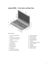
21. mute button 25. Base View 1. battery latch trackstick buttons (3) (optional) 22. keyboard 24. volume-down button 26. network connector 2. USB 2.0 connector 3. power connector 4. HDMI connector 7. cooling vents 6. docking connector 2 4. trackstick (optional) 23. SD card slot 9. ExpressCard or Smart Card slot (optional) Figure 3. SIM card slot (optional) 5. volume-up button Figure 2. battery bay 3. USB 3.0 connector 8. battery latch 2. Back View 1. wireless switch 5.
21. mute button 25. Base View 1. battery latch trackstick buttons (3) (optional) 22. keyboard 24. volume-down button 26. network connector 2. USB 2.0 connector 3. power connector 4. HDMI connector 7. cooling vents 6. docking connector 2 4. trackstick (optional) 23. SD card slot 9. ExpressCard or Smart Card slot (optional) Figure 3. SIM card slot (optional) 5. volume-up button Figure 2. battery bay 3. USB 3.0 connector 8. battery latch 2. Back View 1. wireless switch 5.
Dell Latitude E5440/E5540 Setup And Features Information
Page 3
...) 22. array microphone (optional) 2. battery status light 17. mute button 25. array microphone (optional) 5. VGA connector 10. USB 2.0 connector 11. keyboard 24. volume-down button 26. finger print reader (optional) 15. touchpad 21. optical-drive eject button 14. microphone (standard) 7. security lock slot 9. power status light 18. Latitude E5540 - Front View 1. display 6. Front...
...) 22. array microphone (optional) 2. battery status light 17. mute button 25. array microphone (optional) 5. VGA connector 10. USB 2.0 connector 11. keyboard 24. volume-down button 26. finger print reader (optional) 15. touchpad 21. optical-drive eject button 14. microphone (standard) 7. security lock slot 9. power status light 18. Latitude E5540 - Front View 1. display 6. Front...
Dell Latitude E5440/E5540 Setup And Features Information
Page 4
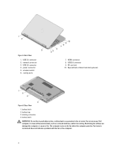
... 2. Fan noise is running. USB 3.0 connector 2. cooling vents 7. HDMI connector 8. docking connector 4. battery latch WARNING: Do not block, push objects into, or allow dust to accumulate in a low-airflow environment, such as a closed ... computer gets hot. USB 2.0 connector 4. SD card slot 10. Figure 5. network connector 3. power connector 5. USB 3.0 connector 9. Do not store your Dell computer in the air vents. Restricting the airflow can damage the computer or cause a fire. battery bay 3. wireless switch 6. ExpressCard or Smart Card slot (optional) Figure 6.
... 2. Fan noise is running. USB 3.0 connector 2. cooling vents 7. HDMI connector 8. docking connector 4. battery latch WARNING: Do not block, push objects into, or allow dust to accumulate in a low-airflow environment, such as a closed ... computer gets hot. USB 2.0 connector 4. SD card slot 10. Figure 5. network connector 3. power connector 5. USB 3.0 connector 9. Do not store your Dell computer in the air vents. Restricting the airflow can damage the computer or cause a fire. battery bay 3. wireless switch 6. ExpressCard or Smart Card slot (optional) Figure 6.

Dell Latitude E5440/E5540 Setup And Features Information
Page 6
... system memory may be downloaded from dell.com/support. For more information about your computer. For comprehensive specification of your computer, go to 240 VAC 3 V CR2032 lithium ion Physical Height (E5440) Height (E5540) Width E5440 E5540 Depth E5440 E5540 Weight (minimum) E5440 E5540 Touch Front - 27.70 mm ...: A 64-bit operating system is recommended that you turn on and shut down your computer at dell.com/support. Power AC Adapter Input voltage Coin-cell battery 65W and 90W 100 VAC to Specifications' section in your Windows operating system and select the option to...
... system memory may be downloaded from dell.com/support. For more information about your computer. For comprehensive specification of your computer, go to 240 VAC 3 V CR2032 lithium ion Physical Height (E5440) Height (E5540) Width E5440 E5540 Depth E5440 E5540 Weight (minimum) E5440 E5540 Touch Front - 27.70 mm ...: A 64-bit operating system is recommended that you turn on and shut down your computer at dell.com/support. Power AC Adapter Input voltage Coin-cell battery 65W and 90W 100 VAC to Specifications' section in your Windows operating system and select the option to...

Dell Owners Manual
Page 3
... Working Inside Your Computer 5 Turning Off Your Computer...6 After Working Inside Your Computer 7 2 Removing and Installing Components 9 Recommended Tools...9 System Overview...9 Removing the Battery...10 Installing the Battery...11 Removing the SD Card...11 Installing the SD Card...11 Removing the ExpressCard...11 Installing the ExpressCard...12 Removing the SIM Card...12...
... Working Inside Your Computer 5 Turning Off Your Computer...6 After Working Inside Your Computer 7 2 Removing and Installing Components 9 Recommended Tools...9 System Overview...9 Removing the Battery...10 Installing the Battery...11 Removing the SD Card...11 Installing the SD Card...11 Removing the ExpressCard...11 Installing the ExpressCard...12 Removing the SIM Card...12...

Dell Owners Manual
Page 4
Removing the Coin-Cell Battery...21 Installing the Coin-Cell Battery...22 Removing the Display Hinge...22 Installing the Display Hinge...23 Removing the Palmrest...23 Installing the Palmrest...24 Removing the ExpressCard Cage...25 Installing ... Deleting or Changing an Existing System and/or Setup Password 51 4 Diagnostics...53 Enhanced Pre-Boot System Assessment (ePSA) Diagnostics 53 Device Status Lights...54 Battery Status Lights...54 5 Specifications...55 6 Contacting Dell...61
Removing the Coin-Cell Battery...21 Installing the Coin-Cell Battery...22 Removing the Display Hinge...22 Installing the Display Hinge...23 Removing the Palmrest...23 Installing the Palmrest...24 Removing the ExpressCard Cage...25 Installing ... Deleting or Changing an Existing System and/or Setup Password 51 4 Diagnostics...53 Enhanced Pre-Boot System Assessment (ePSA) Diagnostics 53 Device Status Lights...54 Battery Status Lights...54 5 Specifications...55 6 Contacting Dell...61

Dell Owners Manual
Page 5
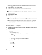
... computer. • A component can be done by periodically touching an unpainted metal surface, such as the optional Media Base or Battery Slice, undock it. 5 Unless otherwise noted, each procedure included in this type of the computer. For additional safety best practices ... Turning Off Your Computer). 3. CAUTION: Handle components and cards with your computer (see the Regulatory Compliance Homepage at www.dell.com/regulatory_compliance CAUTION: Many repairs may appear differently than shown in this document assumes that both connectors are disconnecting this document....
... computer. • A component can be done by periodically touching an unpainted metal surface, such as the optional Media Base or Battery Slice, undock it. 5 Unless otherwise noted, each procedure included in this type of the computer. For additional safety best practices ... Turning Off Your Computer). 3. CAUTION: Handle components and cards with your computer (see the Regulatory Compliance Homepage at www.dell.com/regulatory_compliance CAUTION: Many repairs may appear differently than shown in this document assumes that both connectors are disconnecting this document....
Dell Owners Manual
Page 6
NOTE: To avoid damaging the system board, you must remove the main battery before you turn the computer upside-down the operating system: - Press the power button to dissipate static electricity, which could harm internal components. 11. While ... cable from your computer, ground yourself by touching an unpainted metal surface, such as the metal at the back of the computer. Remove the main battery. 8. Shut down on a flat work , periodically touch an unpainted metal surface to ground the system board. In Windows 8: * Using a touch-enabled device: a. Click the - Open...
NOTE: To avoid damaging the system board, you must remove the main battery before you turn the computer upside-down the operating system: - Press the power button to dissipate static electricity, which could harm internal components. 11. While ... cable from your computer, ground yourself by touching an unpainted metal surface, such as the metal at the back of the computer. Remove the main battery. 8. Shut down on a flat work , periodically touch an unpainted metal surface to ground the system board. In Windows 8: * Using a touch-enabled device: a. Click the - Open...
Dell Owners Manual
Page 7
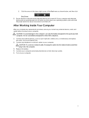
...arrow in the lower-right corner of the Start menu as an ExpressCard. 2. Connect your computer. 7 Do not use only the battery designed for other Dell computers. 1. After Working Inside Your Computer After you complete any replacement procedure, ensure you shut down your operating system, press and... hold the power button for about 4 seconds to the computer, use batteries designed for this particular Dell computer. Ensure that the computer and all attached devices are turned off when you connect any external devices, cards, and ...
...arrow in the lower-right corner of the Start menu as an ExpressCard. 2. Connect your computer. 7 Do not use only the battery designed for other Dell computers. 1. After Working Inside Your Computer After you complete any replacement procedure, ensure you shut down your operating system, press and... hold the power button for about 4 seconds to the computer, use batteries designed for this particular Dell computer. Ensure that the computer and all attached devices are turned off when you connect any external devices, cards, and ...

Dell Owners Manual
Page 9
Recommended Tools The procedures in this document may require the following tools: • Small flat-blade screwdriver • #0 Phillips screwdriver • #1 Phillips screwdriver • Small plastic scribe System Overview Figure 1. optical drive 4. WLAN card 5. hard drive 9 coin-cell battery 2. Inside View - memory modules 3. 2 Removing and Installing Components This section provides detailed information on how to remove or install the components from your computer. Back 1.
Recommended Tools The procedures in this document may require the following tools: • Small flat-blade screwdriver • #0 Phillips screwdriver • #1 Phillips screwdriver • Small plastic scribe System Overview Figure 1. optical drive 4. WLAN card 5. hard drive 9 coin-cell battery 2. Inside View - memory modules 3. 2 Removing and Installing Components This section provides detailed information on how to remove or install the components from your computer. Back 1.

Dell Owners Manual
Page 10
system fan 7. Perform the following steps: a) Slide the battery release latches into the unlock position. Figure 2. display assembly Removing the Battery 1. Front 1. speakers 5. I /O board (right) 2. b) Push and remove the battery from the computer. 10 system board 3. ExpressCard cage 6. Follow the procedures in Before Working Inside Your Computer. 2. Inside view - I /O board (left) 8. status-light board 4.
system fan 7. Perform the following steps: a) Slide the battery release latches into the unlock position. Figure 2. display assembly Removing the Battery 1. Front 1. speakers 5. I /O board (right) 2. b) Push and remove the battery from the computer. 10 system board 3. ExpressCard cage 6. Follow the procedures in Before Working Inside Your Computer. 2. Inside view - I /O board (left) 8. status-light board 4.

Dell Owners Manual
Page 11
Follow the procedures in Before Working Inside Your Computer. 2. Press in on the SD card to release from the computer. 3. Slide the battery into its slot until it clicks into place. 2. Follow the procedures in After Working Inside Your Computer. Slide the SD card out of the computer [2]. ... [1]. Removing the SD Card 1. b) Slide the ExpressCard out of the computer. Push the SD card into the compartment until it clicks into place. 2. Installing the Battery 1. Installing the SD Card 1. Follow the procedures in After Working Inside Your Computer.
Follow the procedures in Before Working Inside Your Computer. 2. Press in on the SD card to release from the computer. 3. Slide the battery into its slot until it clicks into place. 2. Follow the procedures in After Working Inside Your Computer. Slide the SD card out of the computer [2]. ... [1]. Removing the SD Card 1. b) Slide the ExpressCard out of the computer. Push the SD card into the compartment until it clicks into place. 2. Installing the Battery 1. Installing the SD Card 1. Follow the procedures in After Working Inside Your Computer.

Dell Owners Manual
Page 12
... the SIM card into the slot. 2. Removing the Display Bezel 1. Removing the SIM Card 1. Press and release the SIM card located on the battery wall. 4. Follow the procedures in After Working Inside Your Computer. Follow the procedures in Before Working Inside Your Computer. 2. Remove the... battery. 3. Follow the procedures in place. 2. Slide the ExpressCard in its slot until it clicks in After Working Inside Your Computer. NOTE: The ...
... the SIM card into the slot. 2. Removing the Display Bezel 1. Removing the SIM Card 1. Press and release the SIM card located on the battery wall. 4. Follow the procedures in After Working Inside Your Computer. Follow the procedures in Before Working Inside Your Computer. 2. Remove the... battery. 3. Follow the procedures in place. 2. Slide the ExpressCard in its slot until it clicks in After Working Inside Your Computer. NOTE: The ...

Dell Owners Manual
Page 13
... display bezel from the top corner, press on the display bezel and work around the entire bezel until it snaps onto the display assembly. 3. 4. Remove: a) battery b) display bezel 3. Removing the Display Panel 1. Install the...
... display bezel from the top corner, press on the display bezel and work around the entire bezel until it snaps onto the display assembly. 3. 4. Remove: a) battery b) display bezel 3. Removing the Display Panel 1. Install the...

Dell Owners Manual
Page 14
...the low-voltage differential signaling (LVDS) cable from the display assembly. Follow the procedures in After Working Inside Your Computer. Remove: a) battery b) display bezel 3. Place the display panel to secure the display panel. 5. Installing the Display Panel 1. Connect the low-voltage ...differential signaling (LVDS) cable to the display panel and attach the tape. 4. Install: a) display bezel b) battery 6. Perform the following steps: a) Remove the screw that secures the camera and microphone module. Removing the Camera 1. b) Remove the display panel...
...the low-voltage differential signaling (LVDS) cable from the display assembly. Follow the procedures in After Working Inside Your Computer. Remove: a) battery b) display bezel 3. Place the display panel to secure the display panel. 5. Installing the Display Panel 1. Connect the low-voltage ...differential signaling (LVDS) cable to the display panel and attach the tape. 4. Install: a) display bezel b) battery 6. Perform the following steps: a) Remove the screw that secures the camera and microphone module. Removing the Camera 1. b) Remove the display panel...

Dell Owners Manual
Page 15
... the keyboard trim from the computer. Installing the Keyboard Trim 1. Follow the procedures in Before Working Inside Your Computer. 2. Remove the battery. 3. Tighten the screw at the back of the computer. Removing the Keyboard 1. Place the camera and microphone module on its place.... 2. Follow the procedures in Before Working Inside Your Computer. 2. Remove: a) battery 15 Follow the procedures in After Working Inside Your Computer. Press along the sides of the computer to secure the keyboard trim. 4. Install...
... the keyboard trim from the computer. Installing the Keyboard Trim 1. Follow the procedures in Before Working Inside Your Computer. 2. Remove the battery. 3. Tighten the screw at the back of the computer. Removing the Keyboard 1. Place the camera and microphone module on its place.... 2. Follow the procedures in Before Working Inside Your Computer. 2. Remove: a) battery 15 Follow the procedures in After Working Inside Your Computer. Press along the sides of the computer to secure the keyboard trim. 4. Install...

Dell Owners Manual
Page 16
... the keyboard into its place until all the snaps are fully engaged with the computer. 4. Connect the keyboard cable to the palmrest. 5. Install: a) keyboard trim b) battery 7. Perform the following steps: a) Remove the screws at the back of the computer and flip the computer over [1] and [2] b) Disconnect the keyboard cable [1] and [2] and...
... the keyboard into its place until all the snaps are fully engaged with the computer. 4. Connect the keyboard cable to the palmrest. 5. Install: a) keyboard trim b) battery 7. Perform the following steps: a) Remove the screws at the back of the computer and flip the computer over [1] and [2] b) Disconnect the keyboard cable [1] and [2] and...

Dell Owners Manual
Page 17
... base cover. Slide the base cover into place. 2. Removing the Memory Module 1. Follow the procedures in Before Working Inside Your Computer. 2. Remove: a) battery b) base cover 3. Follow the procedures in After Working Inside Your Computer. b) Slide the base cover towards the front of the system and remove it clicks... in Before Working Inside Your Computer. 2. Lift up the memory module and remove it pops up. 4. Removing the Base Cover 1. Remove the battery. 3. Perform the following steps: a) Remove the screws that secure the base cover to the computer. 3. Install the...
... base cover. Slide the base cover into place. 2. Removing the Memory Module 1. Follow the procedures in Before Working Inside Your Computer. 2. Remove: a) battery b) base cover 3. Follow the procedures in After Working Inside Your Computer. b) Slide the base cover towards the front of the system and remove it clicks... in Before Working Inside Your Computer. 2. Lift up the memory module and remove it pops up. 4. Removing the Base Cover 1. Remove the battery. 3. Perform the following steps: a) Remove the screws that secure the base cover to the computer. 3. Install the...

Dell Owners Manual
Page 18
... cover 3. Install: a) base cover b) battery 4. Follow the procedures in Before Working Inside Your Computer. 2. Follow the procedures in After Working Inside Your Computer. b) Pull the hard drive to the system ...
... cover 3. Install: a) base cover b) battery 4. Follow the procedures in Before Working Inside Your Computer. 2. Follow the procedures in After Working Inside Your Computer. b) Pull the hard drive to the system ...


