User Manual
Page 3
... Removing the Display Assembly...31 Installing the Display Assembly...32 Removing the Right Support Frame...33 Installing the Right Support Frame...34 Removing The Modem Card...34 Installing the Modem Card...35 Removing the Left Support Frame...35 Installing the Left Support Frame...36 Removing the System Board...37 Installing the System Board...39...
... Removing the Display Assembly...31 Installing the Display Assembly...32 Removing the Right Support Frame...33 Installing the Right Support Frame...34 Removing The Modem Card...34 Installing the Modem Card...35 Removing the Left Support Frame...35 Installing the Left Support Frame...36 Removing the System Board...37 Installing the System Board...39...

User Manual
Page 5
... safety best practices information, see Turning Off Your Computer). Some cables have read the safety information that is not authorized by Dell is not covered by your warranty. NOTE: The color of the computer. To avoid damaging your computer, perform the following steps...you begin working inside your computer, ground yourself by the online or telephone service and support team. You should only perform troubleshooting and simple repairs as the metal at www.dell.com/ regulatory_compliance CAUTION: Many repairs may appear differently than shown in reverse order. Damage...
... safety best practices information, see Turning Off Your Computer). Some cables have read the safety information that is not authorized by Dell is not covered by your warranty. NOTE: The color of the computer. To avoid damaging your computer, perform the following steps...you begin working inside your computer, ground yourself by the online or telephone service and support team. You should only perform troubleshooting and simple repairs as the metal at www.dell.com/ regulatory_compliance CAUTION: Many repairs may appear differently than shown in reverse order. Damage...
User Manual
Page 33
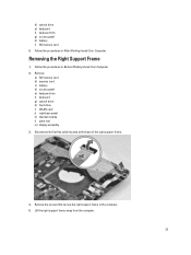
...drive e) keyboard f) keyboard trim g) access panel h) battery i) SD memory card 6. Disconnect the flat flex cable located at the base of the right support frame. 4. Remove: a) SD memory card b) express card c) battery d) access panel e) keyboard trim f) keyboard g) optical drive h) hard drive i)... WLAN card j) right base panel k) thermal module l) palm rest m) display assembly 3. Removing the Right Support Frame 1. Lift the right support frame away from the computer. 33 Follow the procedures in Before Working Inside Your Computer. 2. Follow the procedures in After Working...
...drive e) keyboard f) keyboard trim g) access panel h) battery i) SD memory card 6. Disconnect the flat flex cable located at the base of the right support frame. 4. Remove: a) SD memory card b) express card c) battery d) access panel e) keyboard trim f) keyboard g) optical drive h) hard drive i)... WLAN card j) right base panel k) thermal module l) palm rest m) display assembly 3. Removing the Right Support Frame 1. Lift the right support frame away from the computer. 33 Follow the procedures in Before Working Inside Your Computer. 2. Follow the procedures in After Working...
User Manual
Page 34
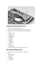
Follow the procedures in Before Working Inside Your Computer. 2. Removing The Modem Card 1. Place the right support frame on the computer. 2. Follow the procedures in After Working Inside Your Computer. Install: a) display assembly b) palm rest c) thermal module d) right base panel e) WLAN card f) ... l) express card m) SD memory card 5. Remove: a) SD memory card b) express card c) battery d) access panel e) keyboard trim f) keyboard 34 Tighten the screws to secure the right support frame to the computer. 3. Connect the flat flex cable located at the base of the right...
Follow the procedures in Before Working Inside Your Computer. 2. Removing The Modem Card 1. Place the right support frame on the computer. 2. Follow the procedures in After Working Inside Your Computer. Install: a) display assembly b) palm rest c) thermal module d) right base panel e) WLAN card f) ... l) express card m) SD memory card 5. Remove: a) SD memory card b) express card c) battery d) access panel e) keyboard trim f) keyboard 34 Tighten the screws to secure the right support frame to the computer. 3. Connect the flat flex cable located at the base of the right...
User Manual
Page 35
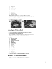
...card. 5. Lift the modem card from the modem card. 6. Engage the modem card to the computer. 4. Removing the Left Support Frame 1. Disconnect the RJ11 cable from the computer. Tighten the screw to secure the modem card to the modem card. 3. Installing... the Modem Card 1. Connect the RJ11 cable to the computer. 5. Follow the procedures in Before Working Inside Your Computer. 2. Install: a) right support frame b) display assembly c) express card reader cage d) palm rest e) thermal module f) right base panel g) hard drive h) optical drive i) keyboard j) keyboard...
...card. 5. Lift the modem card from the modem card. 6. Engage the modem card to the computer. 4. Removing the Left Support Frame 1. Disconnect the RJ11 cable from the computer. Tighten the screw to secure the modem card to the modem card. 3. Installing... the Modem Card 1. Connect the RJ11 cable to the computer. 5. Follow the procedures in Before Working Inside Your Computer. 2. Install: a) right support frame b) display assembly c) express card reader cage d) palm rest e) thermal module f) right base panel g) hard drive h) optical drive i) keyboard j) keyboard...
User Manual
Page 36
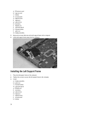
... g) optical drive h) hard drive i) WLAN card j) right base panel k) thermal module l) palm rest m) display assembly 3. Remove the screws that secure the left support frame to the computer. 4. Installing the Left Support Frame 1. Install: a) display assembly b) palm rest c) thermal module d) right base panel e) WLAN card f) hard drive g) optical drive h) keyboard i) keyboard trim j) access...
... g) optical drive h) hard drive i) WLAN card j) right base panel k) thermal module l) palm rest m) display assembly 3. Remove the screws that secure the left support frame to the computer. 4. Installing the Left Support Frame 1. Install: a) display assembly b) palm rest c) thermal module d) right base panel e) WLAN card f) hard drive g) optical drive h) keyboard i) keyboard trim j) access...
User Manual
Page 37
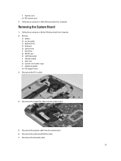
... b) access panel c) keyboard trim d) keyboard e) optical drive f) hard drive g) WLAN card h) right base panel i) thermal module j) palm rest k) express card reader cage l) display assembly m) left support frame 3. Disconnect the audio board flat flex cable. 7. Disconnect the DC-in After Working Inside Your Computer. Disconnect the speaker cable from the system board...
... b) access panel c) keyboard trim d) keyboard e) optical drive f) hard drive g) WLAN card h) right base panel i) thermal module j) palm rest k) express card reader cage l) display assembly m) left support frame 3. Disconnect the audio board flat flex cable. 7. Disconnect the DC-in After Working Inside Your Computer. Disconnect the speaker cable from the system board...

User Manual
Page 39
Align the system board into its original position on the left support frame b) display assembly c) express card reader cage 39 Replace and tighten the screws to secure the system board to the computer. 3. Route and connect the following cables the system board: a) audio board flat flex cable b) bluetooth cable c) speaker cable d) DC-in cable e) thermal fan cable 4. 10. Install: a) left and remove the system board. Installing the System Board 1. Release the system board from the port connectors on the computer. 2.
Align the system board into its original position on the left support frame b) display assembly c) express card reader cage 39 Replace and tighten the screws to secure the system board to the computer. 3. Route and connect the following cables the system board: a) audio board flat flex cable b) bluetooth cable c) speaker cable d) DC-in cable e) thermal fan cable 4. 10. Install: a) left and remove the system board. Installing the System Board 1. Release the system board from the port connectors on the computer. 2.
User Manual
Page 40
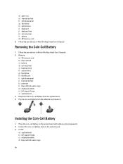
...optical drive g) hard drive h) WLAN card i) right base panel j) thermal module k) palmrest l) ExpressCard reader cage m) display assembly n) left support frame c) display assembly d) ExpressCard reader cage 40 Place the coin-cell battery on the system board with adhesive side downwards. 2. Installing the ...Coin-Cell Battery 1. Pry the coin-cell battery from the system board. 4. Install: a) system board b) left support frame o) system board 3. d) palm rest e) thermal module f) right base panel g) hard drive h) optical drive i) keyboard j) keyboard trim k)...
...optical drive g) hard drive h) WLAN card i) right base panel j) thermal module k) palmrest l) ExpressCard reader cage m) display assembly n) left support frame c) display assembly d) ExpressCard reader cage 40 Place the coin-cell battery on the system board with adhesive side downwards. 2. Installing the ...Coin-Cell Battery 1. Pry the coin-cell battery from the system board. 4. Install: a) system board b) left support frame o) system board 3. d) palm rest e) thermal module f) right base panel g) hard drive h) optical drive i) keyboard j) keyboard trim k)...
User Manual
Page 41
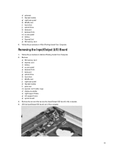
... panel e) keyboard trim f) keyboard g) optical drive h) hard drive i) WLAN card j) right base panel k) thermal module l) palm rest m) express card reader cage n) display assembly o) right support frame p) left support frame q) system board 3. Lift the Input/Output (IO) board out of the computer. 41 Follow the procedures in After Working Inside Your Computer. e) palmrest...
... panel e) keyboard trim f) keyboard g) optical drive h) hard drive i) WLAN card j) right base panel k) thermal module l) palm rest m) express card reader cage n) display assembly o) right support frame p) left support frame q) system board 3. Lift the Input/Output (IO) board out of the computer. 41 Follow the procedures in After Working Inside Your Computer. e) palmrest...
User Manual
Page 42
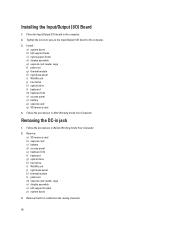
... the DC-in Before Working Inside Your Computer. 2. Follow the procedures in After Working Inside Your Computer. Install: a) system board b) left support bracket p) system board 3. Remove: a) SD memory card b) express card c) battery d) access panel e) keyboard trim f) keyboard g) optical ...drive h) hard drive i) WLAN card j) right base panel k) thermal module l) palm rest m) express card reader cage n) display assembly o) left support frame c) right support frame d) display assembly e) express card reader cage f) palm rest g) thermal module h) right base panel i) WLAN card j) hard drive k) ...
... the DC-in Before Working Inside Your Computer. 2. Follow the procedures in After Working Inside Your Computer. Install: a) system board b) left support bracket p) system board 3. Remove: a) SD memory card b) express card c) battery d) access panel e) keyboard trim f) keyboard g) optical ...drive h) hard drive i) WLAN card j) right base panel k) thermal module l) palm rest m) express card reader cage n) display assembly o) left support frame c) right support frame d) display assembly e) express card reader cage f) palm rest g) thermal module h) right base panel i) WLAN card j) hard drive k) ...

User Manual
Page 43
4. Install the DC-in jack in Jack 1. Install: a) system board b) left support bracket c) display assembly d) express card reader cage e) palm rest f) thermal module g) right base panel h) WLAN card i) hard drive 43 Installing the DC-in the computer. 2. Remove the DC-in the routing channel. 3. Thread the DC-in cable in -jack.
4. Install the DC-in jack in Jack 1. Install: a) system board b) left support bracket c) display assembly d) express card reader cage e) palm rest f) thermal module g) right base panel h) WLAN card i) hard drive 43 Installing the DC-in the computer. 2. Remove the DC-in the routing channel. 3. Thread the DC-in cable in -jack.
User Manual
Page 44
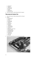
... panel e) keyboard trim f) keyboard g) optical drive h) hard drive i) WLAN card j) right base panel k) thermal module l) palm rest m) express card reader cage n) display assembly o) right support frame p) left support frame q) modem card r) system board s) DC-in After Working Inside Your Computer. Removing the System Fan 1. Follow the procedures in Before Working Inside Your...
... panel e) keyboard trim f) keyboard g) optical drive h) hard drive i) WLAN card j) right base panel k) thermal module l) palm rest m) express card reader cage n) display assembly o) right support frame p) left support frame q) modem card r) system board s) DC-in After Working Inside Your Computer. Removing the System Fan 1. Follow the procedures in Before Working Inside Your...

User Manual
Page 45
Place the system fan in the computer. 3. Tighten the screws to secure the fan in the computer. 2. Install: a) RJ11 jack b) DC-in After Working Inside Your Computer. 45 Follow the procedures in -jack c) system board d) modem card e) left support frame f) right support frame g) display assembly h) express card reader cage i) palm rest j) thermal module k) right base panel l) WLAN card m) hard drive n) optical drive o) keyboard p) keyboard trim q) access panel r) battery s) express card t) SD memory card 4. 4. Lift the system fan out of the computer. Installing the System Fan 1.
Place the system fan in the computer. 3. Tighten the screws to secure the fan in the computer. 2. Install: a) RJ11 jack b) DC-in After Working Inside Your Computer. 45 Follow the procedures in -jack c) system board d) modem card e) left support frame f) right support frame g) display assembly h) express card reader cage i) palm rest j) thermal module k) right base panel l) WLAN card m) hard drive n) optical drive o) keyboard p) keyboard trim q) access panel r) battery s) express card t) SD memory card 4. 4. Lift the system fan out of the computer. Installing the System Fan 1.
User Manual
Page 46
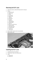
... d) access panel e) keyboard trim f) keyboard g) optical drive h) hard drive i) WLAN card j) right base panel k) thermal module l) palm rest m) express card reader cage n) display assembly o) right support frame p) left support frame q) modem card r) system board 3. Removing the RJ11 Jack 1. Remove the RJ11 cables from the routing channels. 4.
... d) access panel e) keyboard trim f) keyboard g) optical drive h) hard drive i) WLAN card j) right base panel k) thermal module l) palm rest m) express card reader cage n) display assembly o) right support frame p) left support frame q) modem card r) system board 3. Removing the RJ11 Jack 1. Remove the RJ11 cables from the routing channels. 4.

User Manual
Page 47
... g) optical drive h) hard drive i) WLAN card j) right base panel k) thermal module l) palm rest m) express card reader cage n) bluetooth module o) audio board p) LCD assembly q) left support frame d) right support frame e) display assembly f) express card reader cage g) palm rest h) thermal module i) right base panel j) WLAN card k) hard drive l) optical drive m) keyboard n) keyboard trim o) access...
... g) optical drive h) hard drive i) WLAN card j) right base panel k) thermal module l) palm rest m) express card reader cage n) bluetooth module o) audio board p) LCD assembly q) left support frame d) right support frame e) display assembly f) express card reader cage g) palm rest h) thermal module i) right base panel j) WLAN card k) hard drive l) optical drive m) keyboard n) keyboard trim o) access...

User Manual
Page 48
Installing the Speakers 1. Place the speakers in the routing channels. 4. Remove the speaker cables from the computer. Install: a) system board b) left support frame c) display assembly d) audio board e) bluetooth module f) express card reader cage 48 4. Connect the speaker cables and secure it in the computer. 2. Lift the speaker out from the routing channels. 5. Tighten the screws to secure the speakers to the computer. 3.
Installing the Speakers 1. Place the speakers in the routing channels. 4. Remove the speaker cables from the computer. Install: a) system board b) left support frame c) display assembly d) audio board e) bluetooth module f) express card reader cage 48 4. Connect the speaker cables and secure it in the computer. 2. Lift the speaker out from the routing channels. 5. Tighten the screws to secure the speakers to the computer. 3.
User Manual
Page 51
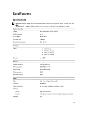
... computer. Specifications Specifications NOTE: Offerings may vary by region. For more information regarding the configuration of your computer, click Start (Start icon) → Help and Support, and then select the option to -analog) high definition audio microphone-in/stereo headphones/external speakers connector two 51
... computer. Specifications Specifications NOTE: Offerings may vary by region. For more information regarding the configuration of your computer, click Start (Start icon) → Help and Support, and then select the option to -analog) high definition audio microphone-in/stereo headphones/external speakers connector two 51
User Manual
Page 61
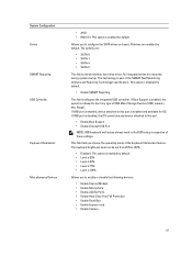
... is 25% • Level is 50% • Level is 75% • Level is 100% Allows you to this port. • Enable Boot Support • Enable External USB Port NOTE: USB keyboard and mouse always work in the BIOS setup irrespective of the SMART (Self Monitoring Analysis and Reporting...errors for OS. This option is enabled by default. If USB port is enabled and available for integrated drives are enabled by default. If Boot Support is enabled, the system is enabled, device attached to enable or disable the following devices: • Enable Internal Modem • Enable Microphone ...
... is 25% • Level is 50% • Level is 75% • Level is 100% Allows you to this port. • Enable Boot Support • Enable External USB Port NOTE: USB keyboard and mouse always work in the BIOS setup irrespective of the SMART (Self Monitoring Analysis and Reporting...errors for OS. This option is enabled by default. If USB port is enabled and available for integrated drives are enabled by default. If Boot Support is enabled, the system is enabled, device attached to enable or disable the following devices: • Enable Internal Modem • Enable Microphone ...
User Manual
Page 63
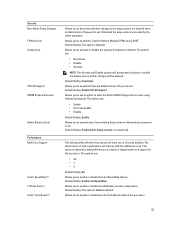
...the admin password. Allows you to enter the Option ROM Configuration screens using hotkeys during POST. Allows you to enable or disable multi-core support for the processor. The options are : • Deactivate • Disable • Activate NOTE: The Activate and Disable options will ...63 Default Setting: Enable Admin Setup Lockout is disabled. Default Setting: The option is not selected. Default Setting: Enable CPU XD Support Allows you to enable or disable the Intel TurboBoost mode of the processor. This field specifies whether the process will improve with the...
...the admin password. Allows you to enter the Option ROM Configuration screens using hotkeys during POST. Allows you to enable or disable multi-core support for the processor. The options are : • Deactivate • Disable • Activate NOTE: The Activate and Disable options will ...63 Default Setting: Enable Admin Setup Lockout is disabled. Default Setting: The option is not selected. Default Setting: Enable CPU XD Support Allows you to enable or disable the Intel TurboBoost mode of the processor. This field specifies whether the process will improve with the...


