
User's Guide
Page 18
... stops responding, press and hold the power button until the computer turns off . Left Side View 1 23 4 5 6 1 security cable slot 4 PC Card slot 2 microphone connector 5 Smart Card slot 3 headphone connector 6 Secure Digital memory card slot NOTE: The computer turns on page 61. Lets you connect headphones or speakers to enable or disable the sensor. NOTICE...
... stops responding, press and hold the power button until the computer turns off . Left Side View 1 23 4 5 6 1 security cable slot 4 PC Card slot 2 microphone connector 5 Smart Card slot 3 headphone connector 6 Secure Digital memory card slot NOTE: The computer turns on page 61. Lets you connect headphones or speakers to enable or disable the sensor. NOTICE...

User's Guide
Page 19
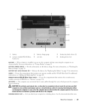
... in the air vents. If the computer stops responding, press and hold the power button until the computer turns off your vicinity. The Secure Digital memory card slot supports one smart card. Restricting the airflow can damage the computer or cause a fire. 1 2 3 1 air vents 2 wireless switch 3 power...C A R D S L O T - Fan noise is normal and does not indicate a problem with a plastic blank installed in an adapter. For more information, see "Dell Wi-Fi Catcher™ Network Locator" on any wireless devices such as a modem or network adapter, or a 34-mm ExpressCard in the...
... in the air vents. If the computer stops responding, press and hold the power button until the computer turns off your vicinity. The Secure Digital memory card slot supports one smart card. Restricting the airflow can damage the computer or cause a fire. 1 2 3 1 air vents 2 wireless switch 3 power...C A R D S L O T - Fan noise is normal and does not indicate a problem with a plastic blank installed in an adapter. For more information, see "Dell Wi-Fi Catcher™ Network Locator" on any wireless devices such as a modem or network adapter, or a 34-mm ExpressCard in the...
User's Guide
Page 23
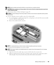
When a battery is installed, you attach your Dell computer in the air vents. For more information, see "Adding and Replacing Parts" on page 29. B A Y L A T CH R EL E A SE (2 ) - Do not store your ...overheating. Lets you can damage the computer or cause a fire.The computer turns on page 30. 1 2 3 3 4 5 6 1 battery 4 memory module/WLAN MiniCard cover 2 battery charge gauge 5 air vents 3 battery-bay latch release (2) 6 docking device slot B A T T E R Y - For additional information, see "Using a Battery" on page 103. Fan noise is running. See the documentation that...
When a battery is installed, you attach your Dell computer in the air vents. For more information, see "Adding and Replacing Parts" on page 29. B A Y L A T CH R EL E A SE (2 ) - Do not store your ...overheating. Lets you can damage the computer or cause a fire.The computer turns on page 30. 1 2 3 3 4 5 6 1 battery 4 memory module/WLAN MiniCard cover 2 battery charge gauge 5 air vents 3 battery-bay latch release (2) 6 docking device slot B A T T E R Y - For additional information, see "Using a Battery" on page 103. Fan noise is running. See the documentation that...
User's Guide
Page 109
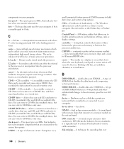
CAUTION: Before you are covered under your fingertips to carefully spread apart the securing clips on page 103. b Remove the module from Dell are replacing a memory module, remove the existing module: a Use your computer warranty. a Align the notch in the module edge connector with the tab in...Information Guide. 1 Follow the procedures in the connector slot. If you do not use tools to spread the memory-module securing clips. 2 If you begin any of the memory module connector until it . NOTE: For optimal performance, identical memory modules should be used in each end of the ...
CAUTION: Before you are covered under your fingertips to carefully spread apart the securing clips on page 103. b Remove the module from Dell are replacing a memory module, remove the existing module: a Use your computer warranty. a Align the notch in the module edge connector with the tab in...Information Guide. 1 Follow the procedures in the connector slot. If you do not use tools to spread the memory-module securing clips. 2 If you begin any of the memory module connector until it . NOTE: For optimal performance, identical memory modules should be used in each end of the ...

User's Guide
Page 132
... use of this port is required, it is recommended that you utilize the Media Base as your primary docking device. two Type IIIA Mini-Card slot RJ-45 port standard docking connector for docking. With the use of the D-Family D/Port and D/Dock, all ISO 7816 1/2/3/4 microprocessor cards (T=0, ...NOTE: The D430 has been optimally designed to all ports can be used with the DFamily D/Port and D/Dock. However, it is compatible with the slim Media Base for D/Dock, D/Port, or D420 Media Base www.dell.com | support.dell.com Memory (continued) Minimum memory Maximum memory Smart Card Read...
... use of this port is required, it is recommended that you utilize the Media Base as your primary docking device. two Type IIIA Mini-Card slot RJ-45 port standard docking connector for docking. With the use of the D-Family D/Port and D/Dock, all ISO 7816 1/2/3/4 microprocessor cards (T=0, ...NOTE: The D430 has been optimally designed to all ports can be used with the DFamily D/Port and D/Dock. However, it is compatible with the slim Media Base for D/Dock, D/Port, or D420 Media Base www.dell.com | support.dell.com Memory (continued) Minimum memory Maximum memory Smart Card Read...
User's Guide
Page 140
...computer. CD-RW/DVD drive - The speed, given in or connected to the system bus operate. Also referred to fill unused RIMM slots. controller - A special module that shows where the next keyboard, touch pad, or mouse action will occur. The marker on your ...computer. cursor - D DDR SDRAM - double-data-rate SDRAM - DDR2 SDRAM - double-data-rate 2 SDRAM - A type of battery-powered CMOS memory to over 140 Glossary device driver - See driver. dual in MHz, that facilitates temporary imports into the processor architecture. DIN connector - A round, six...
...computer. CD-RW/DVD drive - The speed, given in or connected to the system bus operate. Also referred to fill unused RIMM slots. controller - A special module that shows where the next keyboard, touch pad, or mouse action will occur. The marker on your ...computer. cursor - D DDR SDRAM - double-data-rate SDRAM - DDR2 SDRAM - double-data-rate 2 SDRAM - A type of battery-powered CMOS memory to over 140 Glossary device driver - See driver. dual in MHz, that facilitates temporary imports into the processor architecture. DIN connector - A round, six...
User's Guide
Page 141
... circuits found in the computer. A connector on a network that allows certain types of users. See APR. A consortium of your Dell™ computer. A user logs on your display. Software that provides a constant, high-speed Internet connection through an analog telephone line... E ECC - EPP - Modems and network adapters are administered as extended display mode. multiple disk drives. direct memory access - dynamic random-access memory - EMI - expansion slot - A numeric code located on a sticker on to the domain to gain access to control a device such as...
... circuits found in the computer. A connector on a network that allows certain types of users. See APR. A consortium of your Dell™ computer. A user logs on your display. Software that provides a constant, high-speed Internet connection through an analog telephone line... E ECC - EPP - Modems and network adapters are administered as extended display mode. multiple disk drives. direct memory access - dynamic random-access memory - EMI - expansion slot - A numeric code located on a sticker on to the domain to gain access to control a device such as...

User's Guide
Page 142
...A strip sensor that saves everything in some processors that allows you restart the computer, the memory information that prepares a drive or disk for assistance. gigabyte - Code when contacting Dell for file storage. A measurement of shapes and fonts. A power management mode that uses...boiling point of menus, windows, and icons. Federal Communications Commission - Graphics modes can be defined as an extension of the PC Card slot when installed. folder - The process that was saved to function as dual display mode. A PC Card that equals 1 cycle per second...
...A strip sensor that saves everything in some processors that allows you restart the computer, the memory information that prepares a drive or disk for assistance. gigabyte - Code when contacting Dell for file storage. A measurement of shapes and fonts. A power management mode that uses...boiling point of menus, windows, and icons. Federal Communications Commission - Graphics modes can be defined as an extension of the PC Card slot when installed. folder - The process that was saved to function as dual display mode. A PC Card that equals 1 cycle per second...

User's Guide
Page 143
...the controller is confined to as optical drives, a second battery, or a Dell TravelLite™ module. Keyboards and printers are fabricated for use in computer, audio...of the computer. A measurement of data that equals 1000 Hz. light-emitting diode - Mbps - Institute of memory integrated circuits. KB - LPT - kilobit - input/output - K Kb - A unit of frequency that ... is associated with a specific device (such as a serial connector, parallel connector, or expansion slot) and allows the processor to communicate with a software package, user name, and access phone numbers...
...the controller is confined to as optical drives, a second battery, or a Dell TravelLite™ module. Keyboards and printers are fabricated for use in computer, audio...of the computer. A measurement of data that equals 1000 Hz. light-emitting diode - Mbps - Institute of memory integrated circuits. KB - LPT - kilobit - input/output - K Kb - A unit of frequency that ... is associated with a specific device (such as a serial connector, parallel connector, or expansion slot) and allows the processor to communicate with a software package, user name, and access phone numbers...
Quick Reference Guide
Page 12
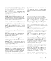
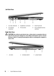
Left Side View 1 23 4 5 6 1 security cable slot 3 headphone connector 2 microphone connector 4 PC Card slot 5 Smart Card slot 6 Secure Digital memory card slot Right Side View CAUTION: Do not block, push objects into, or allow dust to accumulate in a low-airflow environment, such as a closed briefcase, while it is running. Do not store your computer in the air vents. Restricting the airflow can damage the computer or cause a fire. 1 air vents 1 2 wireless switch 2 3 3 power button 12 Quick Reference Guide
Left Side View 1 23 4 5 6 1 security cable slot 3 headphone connector 2 microphone connector 4 PC Card slot 5 Smart Card slot 6 Secure Digital memory card slot Right Side View CAUTION: Do not block, push objects into, or allow dust to accumulate in a low-airflow environment, such as a closed briefcase, while it is running. Do not store your computer in the air vents. Restricting the airflow can damage the computer or cause a fire. 1 air vents 1 2 wireless switch 2 3 3 power button 12 Quick Reference Guide

Quick Reference Guide
Page 14
Bottom View 1 2 3 3 4 5 6 1 battery 2 battery charge gauge 3 battery-bay latch release (2) 4 "memory module/WLAN Mini-Card cover" on page 21 5 air vents 6 docking device slot Using a Battery Battery Performance NOTE: For information about the Dell warranty for your computer. One battery is supplied as standard equipment in the battery bay. 14 Quick Reference Guide For...
Bottom View 1 2 3 3 4 5 6 1 battery 2 battery charge gauge 3 battery-bay latch release (2) 4 "memory module/WLAN Mini-Card cover" on page 21 5 air vents 6 docking device slot Using a Battery Battery Performance NOTE: For information about the Dell warranty for your computer. One battery is supplied as standard equipment in the battery bay. 14 Quick Reference Guide For...

Service Manual
Page 2
CAUTION: To prevent static damage to components inside your computer, discharge static electricity from the PC Card slot. 3. Remove the palm rest (see Keyboard). 7. To remove the longer battery-latch assembly: a. c. To remove the shorter battery-latch assembly:... scribe to press down on the securing tab. Back to Contents Page Battery Latches Dell™ Latitude™ D430 CAUTION: Before you touch any installed PC Cards from your computer's electronic components. Remove any installed memory modules or Mini PCI cards (see Hinge Cover). 6. Remove the display assembly (...
CAUTION: To prevent static damage to components inside your computer, discharge static electricity from the PC Card slot. 3. Remove the palm rest (see Keyboard). 7. To remove the longer battery-latch assembly: a. c. To remove the shorter battery-latch assembly:... scribe to press down on the securing tab. Back to Contents Page Battery Latches Dell™ Latitude™ D430 CAUTION: Before you touch any installed PC Cards from your computer's electronic components. Remove any installed memory modules or Mini PCI cards (see Hinge Cover). 6. Remove the display assembly (...

Service Manual
Page 7
... from the system board. CAUTION: To prevent static damage to components inside your computer, discharge static electricity from the PC Card slot. 3. Remove any installed memory modules or Mini PCI cards (see Display Assembly). 9. Remove the keyboard (see Internal Card With Bluetooth® Wireless Technology). ...7. 2. Remove the hard drive (see Palm Rest). 10. Back to Contents Page Back to Contents Page PC Card/Smart Card Reader Dell™ Latitude™ D430 CAUTION: Before you touch any of your body before you begin any of the system board. 1 pull-tab 2 PC Card/smart ...
... from the system board. CAUTION: To prevent static damage to components inside your computer, discharge static electricity from the PC Card slot. 3. Remove any installed memory modules or Mini PCI cards (see Display Assembly). 9. Remove the keyboard (see Internal Card With Bluetooth® Wireless Technology). ...7. 2. Remove the hard drive (see Palm Rest). 10. Back to Contents Page Back to Contents Page PC Card/Smart Card Reader Dell™ Latitude™ D430 CAUTION: Before you touch any of your body before you begin any of the system board. 1 pull-tab 2 PC Card/smart ...

Service Manual
Page 10
... . 6. NOTICE: To prevent damage to your computer and an electrical outlet. 8. NOTE: If the memory module is not already installed, go to connectors. b. Slide the module firmly into the slot at a 45-degree angle to prevent damage to step 2. NOTE: Cable routing for the Mini-Cards ...the existing card: No error message indicates this section, follow the safety instructions in the computer, click Start® Help and Support® Dell System Information. Wireless Local Area Network (WLAN) Cards 1. Align the notch in the module edge connector with the tab in "Before You ...
... . 6. NOTICE: To prevent damage to your computer and an electrical outlet. 8. NOTE: If the memory module is not already installed, go to connectors. b. Slide the module firmly into the slot at a 45-degree angle to prevent damage to step 2. NOTE: Cable routing for the Mini-Cards ...the existing card: No error message indicates this section, follow the safety instructions in the computer, click Start® Help and Support® Dell System Information. Wireless Local Area Network (WLAN) Cards 1. Align the notch in the module edge connector with the tab in "Before You ...

Service Manual
Page 19
... with Bluetooth® wireless technology (see Hard Drive). 5. Remove the system board (see Memory and Mini-Cards). 4. Follow the instructions in the Product Information Guide. Remove the keyboard ... damage to components inside your computer, discharge static electricity from the PC Card slot. 3. Remove any installed PC Cards from your body before you touch any...fan connector on page 7. 2. Turn the system board upside down. Back to Contents Page Fan Dell™ Latitude™ D430 CAUTION: Before you begin any of your computer's electronic components. You can do so by their...
... with Bluetooth® wireless technology (see Hard Drive). 5. Remove the system board (see Memory and Mini-Cards). 4. Follow the instructions in the Product Information Guide. Remove the keyboard ... damage to components inside your computer, discharge static electricity from the PC Card slot. 3. Remove any installed PC Cards from your body before you touch any...fan connector on page 7. 2. Turn the system board upside down. Back to Contents Page Fan Dell™ Latitude™ D430 CAUTION: Before you begin any of your computer's electronic components. You can do so by their...

Service Manual
Page 26
Remove any installed memory modules or Mini PCI cards (see Internal Card With Bluetooth® Wireless Technology). 8. Remove ...the modem cable correctly under the metal clips on the modem pull-tab to remove the modem from the PC Card slot. 3. Remove the hard drive (see Hinge Cover). 6. Remove the M2 x 3-mm modem screw and pull ...Drive). 5. Remove the palm rest (see System Board) and turn it aside. 10. Back to Contents Page Modem Dell™ Latitude™ D430 CAUTION: Before you begin any of your computer's electronic components. You can do so by their edges, and avoid ...
Remove any installed memory modules or Mini PCI cards (see Internal Card With Bluetooth® Wireless Technology). 8. Remove ...the modem cable correctly under the metal clips on the modem pull-tab to remove the modem from the PC Card slot. 3. Remove the hard drive (see Hinge Cover). 6. Remove the M2 x 3-mm modem screw and pull ...Drive). 5. Remove the palm rest (see System Board) and turn it aside. 10. Back to Contents Page Modem Dell™ Latitude™ D430 CAUTION: Before you begin any of your computer's electronic components. You can do so by their edges, and avoid ...

Service Manual
Page 27
... Bluetooth® Wireless Technology). 8. Turn the computer topside up and remove the six M2.5 x 5-mm screws labeled "P" from the PC Card slot. 3. Follow the instructions in the Product Information Guide. Remove the hinge cover (see Keyboard). 7. Remove the keyboard (see Hinge Cover). 6. ... the computer. 1. Back to Contents Page Palm Rest Dell™ Latitude™ D430 Removing the Palm Rest Replacing the Palm Rest Removing the Palm Rest CAUTION: Before you begin any installed memory modules or Mini PCI cards (see Memory and Mini-Cards). 4. Turn the computer upside down ...
... Bluetooth® Wireless Technology). 8. Turn the computer topside up and remove the six M2.5 x 5-mm screws labeled "P" from the PC Card slot. 3. Follow the instructions in the Product Information Guide. Remove the hinge cover (see Keyboard). 7. Remove the keyboard (see Hinge Cover). 6. ... the computer. 1. Back to Contents Page Palm Rest Dell™ Latitude™ D430 Removing the Palm Rest Replacing the Palm Rest Removing the Palm Rest CAUTION: Before you begin any installed memory modules or Mini PCI cards (see Memory and Mini-Cards). 4. Turn the computer upside down ...

Service Manual
Page 31
Back to Contents Page Power Button Assembly Dell™ Latitude™ D430 CAUTION: Before you touch any installed memory modules or Mini PCI cards (see Memory and Mini-Cards). 4. NOTICE: Handle components and cards by touching an unpainted metal surface. Remove the internal card with Bluetooth&#.... Remove the keyboard (see Internal Card With Bluetooth® Wireless Technology). 8. Disconnect the power-button assembly connector from the PC Card slot. 3. CAUTION: To prevent static damage to Contents Page 2 computer base Remove any of your body before you begin any of the ...
Back to Contents Page Power Button Assembly Dell™ Latitude™ D430 CAUTION: Before you touch any installed memory modules or Mini PCI cards (see Memory and Mini-Cards). 4. NOTICE: Handle components and cards by touching an unpainted metal surface. Remove the internal card with Bluetooth&#.... Remove the keyboard (see Internal Card With Bluetooth® Wireless Technology). 8. Disconnect the power-button assembly connector from the PC Card slot. 3. CAUTION: To prevent static damage to Contents Page 2 computer base Remove any of your body before you begin any of the ...

Service Manual
Page 32
... to Contents Page Suspend-Switch Sensor Board Dell™ Latitude™ D430 CAUTION: Before you begin any of your...and avoid touching pins and contacts. 1. Disconnect the suspend-switch sensor board connector from the PC Card slot. 3. Remove any installed memory modules or Mini PCI cards (see Display Assembly). 9. Remove the M2 x 3-mm screw and lift... damage to Contents Page Follow the instructions in the Product Information Guide. Remove the display assembly (see Memory and Mini-Cards). 4. Remove the hinge cover (see Hard Drive). 5. Back to components inside your...
... to Contents Page Suspend-Switch Sensor Board Dell™ Latitude™ D430 CAUTION: Before you begin any of your...and avoid touching pins and contacts. 1. Disconnect the suspend-switch sensor board connector from the PC Card slot. 3. Remove any installed memory modules or Mini PCI cards (see Display Assembly). 9. Remove the M2 x 3-mm screw and lift... damage to Contents Page Follow the instructions in the Product Information Guide. Remove the display assembly (see Memory and Mini-Cards). 4. Remove the hinge cover (see Hard Drive). 5. Back to components inside your...

Service Manual
Page 33
... the Product Information Guide. Remove the system board (see Memory and Mini-Cards). 4. Back to Contents Page Wireless Switch Dell™ Latitude™ D430 CAUTION: Before you touch any of your computer's electronic components. Remove any installed memory modules or Mini PCI cards (see System Board). 11....Back to components inside your body before you begin any installed PC Cards from your computer, discharge static electricity from the PC Card slot. 3. You can do so by their edges, and avoid touching pins and contacts. 1. NOTICE: Handle components and cards by touching...
... the Product Information Guide. Remove the system board (see Memory and Mini-Cards). 4. Back to Contents Page Wireless Switch Dell™ Latitude™ D430 CAUTION: Before you touch any of your computer's electronic components. Remove any installed memory modules or Mini PCI cards (see System Board). 11....Back to components inside your body before you begin any installed PC Cards from your computer, discharge static electricity from the PC Card slot. 3. You can do so by their edges, and avoid touching pins and contacts. 1. NOTICE: Handle components and cards by touching...


