
Service Manual
Page 5
Recommended Tools 2 Preparing to Work Inside Your Computer 2 Screw Identification and Tightening 3 ZIF Connectors 5 Field-Replaceable Parts and Assemblies 6 Removing Field-Replaceable Parts and Assemblies 12 Hard-Disk Drive Assembly 13 Modular Bay Devices (Diskette Drive, CD-ROM Drive, DVD-ROM Drive, SuperDisk LS-120 Drive, Battery, or ...
Recommended Tools 2 Preparing to Work Inside Your Computer 2 Screw Identification and Tightening 3 ZIF Connectors 5 Field-Replaceable Parts and Assemblies 6 Removing Field-Replaceable Parts and Assemblies 12 Hard-Disk Drive Assembly 13 Modular Bay Devices (Diskette Drive, CD-ROM Drive, DVD-ROM Drive, SuperDisk LS-120 Drive, Battery, or ...

Service Manual
Page 6
Figure 1. Figure 3. Figure 13. Figure 17. Figure 23. Screw Placement Mat With Component Screw Counts and Sizes 4 Parts and Assemblies 6 vi Figure 5. Figure 10. Figure 4. Figure 18. Figure 6. Figure 7. Figure 14. Figure 20. Figure 8. Figure 11. Computer Orientation 1 Main Battery Assembly Removal 3 Screw ...
Figure 1. Figure 3. Figure 13. Figure 17. Figure 23. Screw Placement Mat With Component Screw Counts and Sizes 4 Parts and Assemblies 6 vi Figure 5. Figure 10. Figure 4. Figure 18. Figure 6. Figure 7. Figure 14. Figure 20. Figure 8. Figure 11. Computer Orientation 1 Main Battery Assembly Removal 3 Screw ...
Service Manual
Page 9
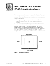
.... A part can be allowed to support it. back of computer left side right side front of the display assembly with respect to the bottom case should never be replaced by performing the removal procedure in your Dell Latitude portable computer.... This manual provides instructions for removing and replacing field-replaceable components, assemblies, and subassemblies in reverse order. When the display assembly is open nearly 180 degrees, use a book or something similar to exceed 180 degrees. The angle of computer support.dell.com Dell Latitude CPt...
.... A part can be allowed to support it. back of computer left side right side front of the display assembly with respect to the bottom case should never be replaced by performing the removal procedure in your Dell Latitude portable computer.... This manual provides instructions for removing and replacing field-replaceable components, assemblies, and subassemblies in reverse order. When the display assembly is open nearly 180 degrees, use a book or something similar to exceed 180 degrees. The angle of computer support.dell.com Dell Latitude CPt...
Service Manual
Page 11
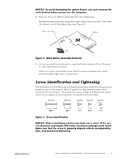
... touch the I /O panel on the back of the computer. M2.5x20 M2.5x10 M3.0x5 M2.5x4 M2.0x3 support.dell.com Dell Latitude CPt V-Series/CPx H-Series Service Manual 3 Then slide the battery out of the computer. Examples are shown in the illustration. Ground... yourself by touching the unpainted metal surface of the screw's label. The illustrations in the following removal procedures provide the correct screw length as part...
... touch the I /O panel on the back of the computer. M2.5x20 M2.5x10 M3.0x5 M2.5x4 M2.0x3 support.dell.com Dell Latitude CPt V-Series/CPx H-Series Service Manual 3 Then slide the battery out of the computer. Examples are shown in the illustration. Ground... yourself by touching the unpainted metal surface of the screw's label. The illustrations in the following removal procedures provide the correct screw length as part...
Service Manual
Page 13
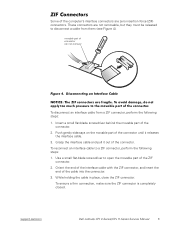
... flat-blade screwdriver to disconnect a cable from a ZIF connector, perform the following steps: 1. support.dell.com Dell Latitude CPt V-Series/CPx H-Series Service Manual 5 Some of the cable into the connector. 3. Insert a small flat-blade screwdriver behind the movable part of connector (do not remove) To disconnect an interface cable from them (see Figure 4). While...
... flat-blade screwdriver to disconnect a cable from a ZIF connector, perform the following steps: 1. support.dell.com Dell Latitude CPt V-Series/CPx H-Series Service Manual 5 Some of the cable into the connector. 3. Insert a small flat-blade screwdriver behind the movable part of connector (do not remove) To disconnect an interface cable from them (see Figure 4). While...
Service Manual
Page 14
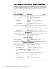
... ASSY, BTM/BZL, CD, 24X, TSHBA ASSY, HSG, PLSTC, CD/DVD, OMHA LBL, CD, MEDIA BAY, TSHB 6 Dell Latitude CPt V-Series/CPx H-Series Service Manual Table 2 lists the parts and assemblies available for removing and replacing these parts and assemblies. Customer kit, AC adapter AC adapter Power cable, U.S. The subsections that follow Table 2 provide instructions...
... ASSY, BTM/BZL, CD, 24X, TSHBA ASSY, HSG, PLSTC, CD/DVD, OMHA LBL, CD, MEDIA BAY, TSHB 6 Dell Latitude CPt V-Series/CPx H-Series Service Manual Table 2 lists the parts and assemblies available for removing and replacing these parts and assemblies. Customer kit, AC adapter AC adapter Power cable, U.S. The subsections that follow Table 2 provide instructions...

Service Manual
Page 20
display assembly keyboard palmrest assembly hard-disk drive system board main battery bottom case assembly modular bay device The following subsections provide instructions for removing and replacing field-replaceable parts and assemblies. 12 Dell Latitude CPt V-Series/CPx H-Series Service Manual
display assembly keyboard palmrest assembly hard-disk drive system board main battery bottom case assembly modular bay device The following subsections provide instructions for removing and replacing field-replaceable parts and assemblies. 12 Dell Latitude CPt V-Series/CPx H-Series Service Manual

Service Manual
Page 45
... removal, 21 display assembly latch removal, 29 display panel, 12.1-inch LCD removal, 25 replacement, 28 display panel, 14.1-inch LCD removal, 23 field-replaceable parts and assemblies illustrated, 12 list of, 6 flex cable, 12.1-inch LCD removal, 26 replacement, 26 flex cable, 14.1-inch LCD removal, 24 grounding to dissipate...
... removal, 21 display assembly latch removal, 29 display panel, 12.1-inch LCD removal, 25 replacement, 28 display panel, 14.1-inch LCD removal, 23 field-replaceable parts and assemblies illustrated, 12 list of, 6 flex cable, 12.1-inch LCD removal, 26 replacement, 26 flex cable, 14.1-inch LCD removal, 24 grounding to dissipate...


