
Service Manual
Page 2
...and trade names may be used in this text: Dell, the DELL logo, and Latitude are registered trademarks and MMX is a trademark of Dell Computer Corporation is strictly forbidden. Intel and Pentium are registered trademarks of Dell Computer Corporation; Trademarks used in this document to refer... to change without the written permission of Intel Corporation; Reproduction in any proprietary interest in trademarks and trade names other than its own. Information in this manual is subject to...
...and trade names may be used in this text: Dell, the DELL logo, and Latitude are registered trademarks and MMX is a trademark of Dell Computer Corporation is strictly forbidden. Intel and Pentium are registered trademarks of Dell Computer Corporation; Trademarks used in this document to refer... to change without the written permission of Intel Corporation; Reproduction in any proprietary interest in trademarks and trade names other than its own. Information in this manual is subject to...
Service Manual
Page 6
...are used as follows: NOTE: A NOTE provides helpful information about using this manual to test the computer system. viii Throughout this manual and the User's Guide that came with the system, Dell provides the Diagnostics and Troubleshooting Guide for using the computer system. A prerequisite...troubleshooting procedures and instructions on using the Dell diagnostics to service Dell computer systems is a basic knowledge of text printed in bold type or in IBM-compatible PC troubleshooting techniques. In addition to information provided in this manual, there may be blocks of IBM&#...
...are used as follows: NOTE: A NOTE provides helpful information about using this manual to test the computer system. viii Throughout this manual and the User's Guide that came with the system, Dell provides the Diagnostics and Troubleshooting Guide for using the computer system. A prerequisite...troubleshooting procedures and instructions on using the Dell diagnostics to service Dell computer systems is a basic knowledge of text printed in bold type or in IBM-compatible PC troubleshooting techniques. In addition to information provided in this manual, there may be blocks of IBM&#...
Service Manual
Page 8
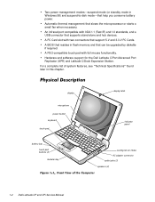
... functionality. A PS/2-compatible touch pad with two connectors that support 5-V and 3.3-V PC Cards. Hardware and software support for the Dell Latitude C/Port Advanced Port Replicator (APR) and Latitude C/Dock Expansion Station. An infrared port compatible with IrDA 1.1 (Fast IR) and 1.0 standards, and a USB connector that slows... pad buttons (2) modular bay display latch indicator panel cooling-fan air intake AC adapter connector audio jacks (3) speakers (2) 1-2 Dell Latitude CP and CPi Service Manual A BIOS that resides in flash memory and that help you conserve battery power.
... functionality. A PS/2-compatible touch pad with two connectors that support 5-V and 3.3-V PC Cards. Hardware and software support for the Dell Latitude C/Port Advanced Port Replicator (APR) and Latitude C/Dock Expansion Station. An infrared port compatible with IrDA 1.1 (Fast IR) and 1.0 standards, and a USB connector that slows... pad buttons (2) modular bay display latch indicator panel cooling-fan air intake AC adapter connector audio jacks (3) speakers (2) 1-2 Dell Latitude CP and CPi Service Manual A BIOS that resides in flash memory and that help you conserve battery power.
Service Manual
Page 10
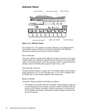
... the functions of these indicators. After the battery is fully charged, the battery indicator blinks green to keep the battery at full capacity. 1-4 Dell Latitude CP and CPi Service Manual The following conditions: The indicator turns green while the AC adapter is either in the modular bay. power indicator drive activity indicator battery indicator...
... the functions of these indicators. After the battery is fully charged, the battery indicator blinks green to keep the battery at full capacity. 1-4 Dell Latitude CP and CPi Service Manual The following conditions: The indicator turns green while the AC adapter is either in the modular bay. power indicator drive activity indicator battery indicator...
Service Manual
Page 12
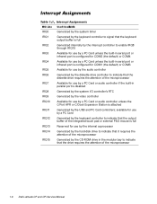
... full Reserved for use by the internal coprocessor Generated by the hard-disk drive to indicate that it requires the attention of the microprocessor 1-6 Dell Latitude CP and CPi Service Manual available for use by a PC Card Generated by the keyboard controller to indicate that the output buffer of the integrated touch pad or...
... full Reserved for use by the internal coprocessor Generated by the hard-disk drive to indicate that it requires the attention of the microprocessor 1-6 Dell Latitude CP and CPi Service Manual available for use by a PC Card Generated by the keyboard controller to indicate that the output buffer of the integrated touch pad or...
Service Manual
Page 14
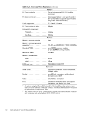
The Microsoft Windows NT ® 4.0 operating system does not support zoom video. 2 The Latitude CP and CPi do not support memory modules from previous models of Dell portable computers, such as the Latitude XP, XPi, XPi CD, and LM. 1-8 Dell Latitude CP and CPi Service Manual PC Card controller Texas Instruments PCI1131 CardBus controller PC Card connectors two (supports...
The Microsoft Windows NT ® 4.0 operating system does not support zoom video. 2 The Latitude CP and CPi do not support memory modules from previous models of Dell portable computers, such as the Latitude XP, XPi, XPi CD, and LM. 1-8 Dell Latitude CP and CPi Service Manual PC Card controller Texas Instruments PCI1131 CardBus controller PC Card connectors two (supports...
Service Manual
Page 16
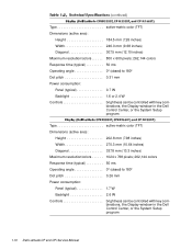
...pitch 0.31 mm Power consumption: Panel (typical 0.7 W Backlight 1.6 or 2.4 W Controls brightness can be controlled with key combinations, the Display window in the Dell Control Center, or the System Setup program Type active-matrix color (TFT) Dimensions (active area): Height 202.8 mm (7.98 inches) Width 270.3 mm (10...Dot pitch 0.26 mm Power consumption: Panel (typical 1.7 W Backlight 2.6 W Controls brightness can be controlled with key combinations, the Display window in the Dell Control Center, or the System Setup program 1-10 Dell Latitude CP and CPi Service Manual
...pitch 0.31 mm Power consumption: Panel (typical 0.7 W Backlight 1.6 or 2.4 W Controls brightness can be controlled with key combinations, the Display window in the Dell Control Center, or the System Setup program Type active-matrix color (TFT) Dimensions (active area): Height 202.8 mm (7.98 inches) Width 270.3 mm (10...Dot pitch 0.26 mm Power consumption: Panel (typical 1.7 W Backlight 2.6 W Controls brightness can be controlled with key combinations, the Display window in the Dell Control Center, or the System Setup program 1-10 Dell Latitude CP and CPi Service Manual
Service Manual
Page 18
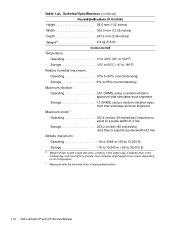
...;F) 3 Battery performance features such as charge time and life span can vary according to the conditions under which the computer and battery are used. 1-12 Dell Latitude CP and CPi Service Manual
...;F) 3 Battery performance features such as charge time and life span can vary according to the conditions under which the computer and battery are used. 1-12 Dell Latitude CP and CPi Service Manual
Service Manual
Page 20
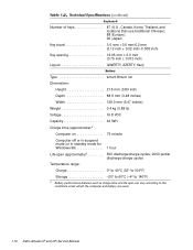
... weigh more or less, depending on its configuration. 7 Measured with a hard-disk drive, a battery in the battery bay, a diskette drive in head-parked position. 1-14 Dell Latitude CP and CPi Service Manual
... weigh more or less, depending on its configuration. 7 Measured with a hard-disk drive, a battery in the battery bay, a diskette drive in head-parked position. 1-14 Dell Latitude CP and CPi Service Manual
Service Manual
Page 22
... slowly). The system is on state. Power indicator is either off the computer, and let the battery and computer cool to -disk mode. 2-2 Dell Latitude CP and CPi Service Manual All indicators remain off . Battery indicator is amber and blinking rapidly when the power switch is pressed or the AC adapter is off . Power...
... slowly). The system is on state. Power indicator is either off the computer, and let the battery and computer cool to -disk mode. 2-2 Dell Latitude CP and CPi Service Manual All indicators remain off . Battery indicator is amber and blinking rapidly when the power switch is pressed or the AC adapter is off . Power...
Service Manual
Page 24
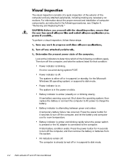
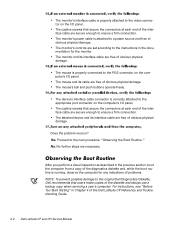
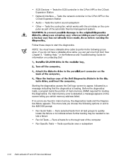
...to the instructions in the documentation for any indications of problems. NOTE: To prevent possible damage to the original Dell Diagnostics Diskette, Dell recommends that users make copies of obvious physical damage. The captive screws that secure the connectors at each end...next procedure, "Observing the Boot Routine." Does the problem reoccur? No further steps are free of the Dell Latitude CP Reference and Troubleshooting Guide. 2-4 Dell Latitude CP and CPi Service Manual Yes. After you perform a visual inspection as described in Chapter 4 of obvious physical damage. The ...
...to the instructions in the documentation for any indications of problems. NOTE: To prevent possible damage to the original Dell Diagnostics Diskette, Dell recommends that users make copies of obvious physical damage. The captive screws that secure the connectors at each end...next procedure, "Observing the Boot Routine." Does the problem reoccur? No further steps are free of the Dell Latitude CP Reference and Troubleshooting Guide. 2-4 Dell Latitude CP and CPi Service Manual Yes. After you perform a visual inspection as described in Chapter 4 of obvious physical damage. The ...
Service Manual
Page 26
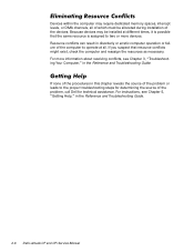
... times, it is assigned to the proper troubleshooting steps for determining the source of the problem, call Dell for technical assistance. If none of the procedures in the Reference and Troubleshooting Guide. 2-6 Dell Latitude CP and CPi Service Manual For instructions, see Chapter 5, "Getting Help," in this chapter reveals the source of the problem or...
... times, it is assigned to the proper troubleshooting steps for determining the source of the problem, call Dell for technical assistance. If none of the procedures in the Reference and Troubleshooting Guide. 2-6 Dell Latitude CP and CPi Service Manual For instructions, see Chapter 5, "Getting Help," in this chapter reveals the source of the problem or...
Service Manual
Page 28
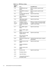
... board faulty Display initialization failure Display retrace test failure No timer tick System board faulty Shutdown failure Gate A20 failure Unexpected interrupt in protected mode 3-2 Dell Latitude CP and CPi Service Manual system board faulty BIOS corrupted;
... board faulty Display initialization failure Display retrace test failure No timer tick System board faulty Shutdown failure Gate A20 failure Unexpected interrupt in protected mode 3-2 Dell Latitude CP and CPi Service Manual system board faulty BIOS corrupted;
Service Manual
Page 30
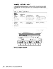
abnormal charge current Fatal Cell imbalance; battery indicator 3-4 Dell Latitude CP and CPi Service Manual Indicator flashes amber four times per second. Temporary Over temperature; Replace the battery. abnormal charge; critical discharge Turn off the computer and let the battery and computer cool to room temperature. abnormal discharge; The following table lists these failure codes. Indicator flashes alternately green and amber. In the event of a battery failure, the battery indicator displays indicator codes that identify the severity of the problem.
abnormal charge current Fatal Cell imbalance; battery indicator 3-4 Dell Latitude CP and CPi Service Manual Indicator flashes amber four times per second. Temporary Over temperature; Replace the battery. abnormal charge; critical discharge Turn off the computer and let the battery and computer cool to room temperature. abnormal discharge; The following table lists these failure codes. Indicator flashes alternately green and amber. In the event of a battery failure, the battery indicator displays indicator codes that identify the severity of the problem.

Service Manual
Page 32
... respond to carry out the command. System board faulty. System board faulty. Computer cannot identify hard-disk drive type. Hard-disk drive faulty. 3-6 Dell Latitude CP and CPi Service Manual Diskette writeprotected. PC Card faulty, improperly seated, or improperly configured. The diskette may be completed. One or more memory modules faulty or improperly seated...
... respond to carry out the command. System board faulty. System board faulty. Computer cannot identify hard-disk drive type. Hard-disk drive faulty. 3-6 Dell Latitude CP and CPi Service Manual Diskette writeprotected. PC Card faulty, improperly seated, or improperly configured. The diskette may be completed. One or more memory modules faulty or improperly seated...

Service Manual
Page 34
...-disk drive from harddisk drive or diskette drive. Operating system boot files missing or corrupted. No operating system files on diskette or hard-disk drive. 3-8 Dell Latitude CP and CPi Service Manual Installed memory module faulty or improperly seated.
...-disk drive from harddisk drive or diskette drive. Operating system boot files missing or corrupted. No operating system files on diskette or hard-disk drive. 3-8 Dell Latitude CP and CPi Service Manual Installed memory module faulty or improperly seated.
Service Manual
Page 36
Tests the built-in the Reference and Troubleshooting Guide for information on contacting Dell. NOTE: You must have a diskette-drive cable, you can get one from all tests for loading the diagnostics. If you do not have a diskette-drive .... If no errors are found in main memory, the diagnostics loads and the Diagnostics Menu appears. Runs selected tests from Dell. Tests a particular area or subsystem 3-10 Dell Latitude CP and CPi Service Manual Runs all test groups to quickly locate the failure or to indicate where further testing may be needed to isolate a failure...
Tests the built-in the Reference and Troubleshooting Guide for information on contacting Dell. NOTE: You must have a diskette-drive cable, you can get one from all tests for loading the diagnostics. If you do not have a diskette-drive .... If no errors are found in main memory, the diagnostics loads and the Diagnostics Menu appears. Runs selected tests from Dell. Tests a particular area or subsystem 3-10 Dell Latitude CP and CPi Service Manual Runs all test groups to quickly locate the failure or to indicate where further testing may be needed to isolate a failure...

Service Manual
Page 38
Most of the procedures in this guide require the use of one or more of the following steps: NOTE: Make sure the computer is turned off and not in suspend-to work on the computer, perform the following tools: Number 1 magnetized Phillips-head screwdriver Small flat-blade screwdriver Small plastic scribe Before you cannot shut down the computer using the computer's operating system, press the power button for 4 seconds. 4-2 Dell Latitude CP and CPi Service Manual If you start to -disk mode.
Most of the procedures in this guide require the use of one or more of the following steps: NOTE: Make sure the computer is turned off and not in suspend-to work on the computer, perform the following tools: Number 1 magnetized Phillips-head screwdriver Small flat-blade screwdriver Small plastic scribe Before you cannot shut down the computer using the computer's operating system, press the power button for 4 seconds. 4-2 Dell Latitude CP and CPi Service Manual If you start to -disk mode.

Service Manual
Page 40
These connectors are zero insertion force (ZIF) connectors. movable part of connector (do not remove) Some of the computer's interface connectors are not removable, but they must be released to disconnect a cable from them To disconnect an interface cable from a ZIF connector, follow these steps: To reconnect an interface cable to a ZIF connector, follow these steps: To ensure a firm connection, make sure the ZIF connector is completely closed. 4-4 Dell Latitude CP and CPi Service Manual
These connectors are zero insertion force (ZIF) connectors. movable part of connector (do not remove) Some of the computer's interface connectors are not removable, but they must be released to disconnect a cable from them To disconnect an interface cable from a ZIF connector, follow these steps: To reconnect an interface cable to a ZIF connector, follow these steps: To ensure a firm connection, make sure the ZIF connector is completely closed. 4-4 Dell Latitude CP and CPi Service Manual
Service Manual
Page 42
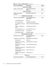
... assembly CBL,FPC,FD,F3,CP interface cable Diskette drive assembly SHLD,FD,F3,CP shield Service kit, exhaust fan SVC,FAN,25X25X10,CP 4-31 4-6 Dell Latitude CP and CPi Service Manual
... assembly CBL,FPC,FD,F3,CP interface cable Diskette drive assembly SHLD,FD,F3,CP shield Service kit, exhaust fan SVC,FAN,25X25X10,CP 4-31 4-6 Dell Latitude CP and CPi Service Manual


