
User Manual
Page 3
Recommended Tools 2 Preparing to Work Inside Your Computer 2 Screw Identification and Tightening 3 ZIF Connectors 4 Field-Replaceable Parts and Assemblies 5 Removing Field-Replaceable Parts and Assemblies 12 Hard-Disk Drive Assembly 13 Memory Module Cover 14 Memory Modules 15 Keyboard Assembly 16 Back Cover Assembly 18 Palmrest Assembly 19 ...
Recommended Tools 2 Preparing to Work Inside Your Computer 2 Screw Identification and Tightening 3 ZIF Connectors 4 Field-Replaceable Parts and Assemblies 5 Removing Field-Replaceable Parts and Assemblies 12 Hard-Disk Drive Assembly 13 Memory Module Cover 14 Memory Modules 15 Keyboard Assembly 16 Back Cover Assembly 18 Palmrest Assembly 19 ...
User Manual
Page 4
Figure 7. Figure 9. Figure 10. Figure 11. Figure 15. Figure 22. Figure 25. Figure 29. Parts and Assemblies 5 vi Figure 8. Figure 12. Figure 16. Figure 17. Figure 18. Figure 26. Figure 27. Figure 14. Figure 20. Figure 24. Figure 4. Figure 13. ...
Figure 7. Figure 9. Figure 10. Figure 11. Figure 15. Figure 22. Figure 25. Figure 29. Parts and Assemblies 5 vi Figure 8. Figure 12. Figure 16. Figure 17. Figure 18. Figure 26. Figure 27. Figure 14. Figure 20. Figure 24. Figure 4. Figure 13. ...
User Manual
Page 7
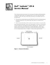
...degrees. A part can be allowed to the bottom case should never be replaced by performing the removal procedure in this chapter assumes the following: The computer and any attached peripherals are turned off, and the peripherals are as shown in your Dell Latitude portable computer....180 degrees, use a book or something similar to the computer are disconnected from the input/output (I/O) panel on the back of computer Dell Latitude CPi A Service Manual 1 Also, when performing the procedures in reverse order. Unless otherwise noted, each procedure in this manual, the locations ...
...degrees. A part can be allowed to the bottom case should never be replaced by performing the removal procedure in this chapter assumes the following: The computer and any attached peripherals are turned off, and the peripherals are as shown in your Dell Latitude portable computer....180 degrees, use a book or something similar to the computer are disconnected from the input/output (I/O) panel on the back of computer Dell Latitude CPi A Service Manual 1 Also, when performing the procedures in reverse order. Unless otherwise noted, each procedure in this manual, the locations ...
User Manual
Page 9
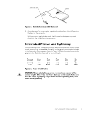
While you work, periodically touch the I /O panel on the back of the computer. A graphic for correct length. The illustrations in the following removal procedures provide the correct screw length as part of the I /O panel to check for that might harm components. Examples are shown in the illustration. 9. Match the actual screw to the graphic in the illustration to dissipate any static electricity that length screw is also included in Figure 3. Ground yourself by touching the unpainted metal surface of the screw's label. Dell Latitude CPi A Service Manual 3
While you work, periodically touch the I /O panel on the back of the computer. A graphic for correct length. The illustrations in the following removal procedures provide the correct screw length as part of the I /O panel to check for that might harm components. Examples are shown in the illustration. 9. Match the actual screw to the graphic in the illustration to dissipate any static electricity that length screw is also included in Figure 3. Ground yourself by touching the unpainted metal surface of the screw's label. Dell Latitude CPi A Service Manual 3
User Manual
Page 10
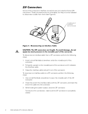
...are zero insertion force (ZIF) connectors. movable part of connector (do not remove) To disconnect an interface cable from them (see Figure 4). To ensure a firm connection, make sure the ZIF connector is completely closed. 4 Dell Latitude CPi A Service Manual Insert a small flat-blade ...screwdriver under the movable part of the cable into the connector. 3. To reconnect an interface cable to a ZIF connector, perform ...
...are zero insertion force (ZIF) connectors. movable part of connector (do not remove) To disconnect an interface cable from them (see Figure 4). To ensure a firm connection, make sure the ZIF connector is completely closed. 4 Dell Latitude CPi A Service Manual Insert a small flat-blade ...screwdriver under the movable part of the cable into the connector. 3. To reconnect an interface cable to a ZIF connector, perform ...
User Manual
Page 11
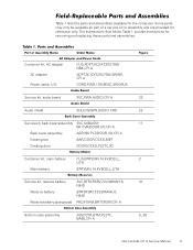
...,7.2V,30MAH,6, NIHD BTRY,RSRV,7.2V,30MAH,6, NIHD PAD,FOAM,BRTY,RSRV,CPi A Bottom case assembly ASSY,CVR,BTM,PLSTC, BASE,CPi A 22 22 11 2 31 5, 26 Dell Latitude CPi A Service Manual 5 Table 1 lists the parts and assemblies available for removing and replacing these parts and assemblies. The subsections that follow Table 1 provide instructions for the computer...
...,7.2V,30MAH,6, NIHD BTRY,RSRV,7.2V,30MAH,6, NIHD PAD,FOAM,BRTY,RSRV,CPi A Bottom case assembly ASSY,CVR,BTM,PLSTC, BASE,CPi A 22 22 11 2 31 5, 26 Dell Latitude CPi A Service Manual 5 Table 1 lists the parts and assemblies available for removing and replacing these parts and assemblies. The subsections that follow Table 1 provide instructions for the computer...
User Manual
Page 18
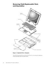
display assembly keyboard palmrest assembly main battery back cover assembly modular bay device bottom case assembly The following subsections provide instructions for removing and replacing field-replaceable parts and assemblies. 12 Dell Latitude CPi A Service Manual
display assembly keyboard palmrest assembly main battery back cover assembly modular bay device bottom case assembly The following subsections provide instructions for removing and replacing field-replaceable parts and assemblies. 12 Dell Latitude CPi A Service Manual
User Manual
Page 49
audio board removal, 31 audio shield removal, 30 back cover assembly removal, 18 battery (in modular bay) removal, 30 bottom case assembly components, 28 illustrated, 29 bottom case bracket removal, 32 CD-ROM drive removal, 30 diskette drive removal, 30 display assembly bezel, removal, 23 removal, 21 top cover, removal, 28 ESD, 2 exhaust fan removal, 39 field-replaceable parts and assemblies illustrated, 12 list of, 5 hard-disk drive assembly removal, 13 I/R board removal, 40 keyboard assembly removal, 16 Index 1
audio board removal, 31 audio shield removal, 30 back cover assembly removal, 18 battery (in modular bay) removal, 30 bottom case assembly components, 28 illustrated, 29 bottom case bracket removal, 32 CD-ROM drive removal, 30 diskette drive removal, 30 display assembly bezel, removal, 23 removal, 21 top cover, removal, 28 ESD, 2 exhaust fan removal, 39 field-replaceable parts and assemblies illustrated, 12 list of, 5 hard-disk drive assembly removal, 13 I/R board removal, 40 keyboard assembly removal, 16 Index 1


