Service Manual
Page 7
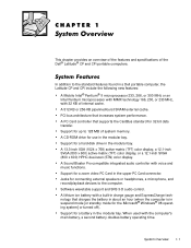
... functions. A PC Card controller that increases system performance. A Sound Blaster Pro-compatible integrated audio controller with the computer's main battery, a second battery doubles battery operating time. Jacks for use in a Dell portable computer, the Latitude CP and CPi include the following new features: A Mobile Intel® Pentium® II microprocessor 233, 266, or 300 MHz or an...
... functions. A PC Card controller that increases system performance. A Sound Blaster Pro-compatible integrated audio controller with the computer's main battery, a second battery doubles battery operating time. Jacks for use in a Dell portable computer, the Latitude CP and CPi include the following new features: A Mobile Intel® Pentium® II microprocessor 233, 266, or 300 MHz or an...
Service Manual
Page 8
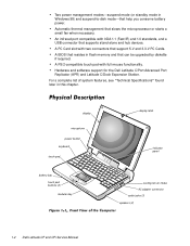
... "Technical Specifications" found later in this chapter. display microphone power button keyboard touch pad battery bay touch pad buttons (2) modular bay display latch indicator panel cooling-fan air intake AC adapter connector audio jacks (3) speakers (2) 1-2 Dell Latitude CP and CPi Service Manual An infrared port compatible with full mouse functionality. Automatic thermal management that support...
... "Technical Specifications" found later in this chapter. display microphone power button keyboard touch pad battery bay touch pad buttons (2) modular bay display latch indicator panel cooling-fan air intake AC adapter connector audio jacks (3) speakers (2) 1-2 Dell Latitude CP and CPi Service Manual An infrared port compatible with full mouse functionality. Automatic thermal management that support...
Service Manual
Page 10
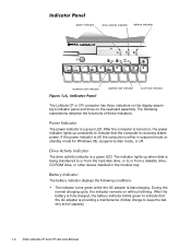
The power indicator is providing a maintenance (trickle) charge to keep the battery at full capacity. 1-4 Dell Latitude CP and CPi Service Manual If the power indicator is off . The following conditions: The indicator turns green while the AC adapter...the computer is fast-charging. After the computer is a green LED. power indicator drive activity indicator battery indicator numbers lock indicator capitals lock indicator scroll lock indicator The Latitude CP or CPi computer has three indicators on the display assembly's indicator panel and three on the keyboard assembly. The...
The power indicator is providing a maintenance (trickle) charge to keep the battery at full capacity. 1-4 Dell Latitude CP and CPi Service Manual If the power indicator is off . The following conditions: The indicator turns green while the AC adapter...the computer is fast-charging. After the computer is a green LED. power indicator drive activity indicator battery indicator numbers lock indicator capitals lock indicator scroll lock indicator The Latitude CP or CPi computer has three indicators on the display assembly's indicator panel and three on the keyboard assembly. The...
Service Manual
Page 11
If no effect on the Latitude CP or CPi computer, C/Dock Expansion Station, or the C/Port APR initiates a change from -disk...enters suspend (or standby mode for a listing of the keyboard. The protocols for 4 seconds causes the computer to "Battery Failure Codes" in suspend mode (or standby mode for Windows 98) (power indicator is off), pressing the power ... off ), the display is closed, and no external monitor is in Chapter 3 for Windows 98). The amber battery indicator lights up without blinking. Refer to power down. The computer remains in suspend mode (or standby mode for...
If no effect on the Latitude CP or CPi computer, C/Dock Expansion Station, or the C/Port APR initiates a change from -disk...enters suspend (or standby mode for a listing of the keyboard. The protocols for 4 seconds causes the computer to "Battery Failure Codes" in suspend mode (or standby mode for Windows 98) (power indicator is off), pressing the power ... off ), the display is closed, and no external monitor is in Chapter 3 for Windows 98). The amber battery indicator lights up without blinking. Refer to power down. The computer remains in suspend mode (or standby mode for...
Service Manual
Page 18
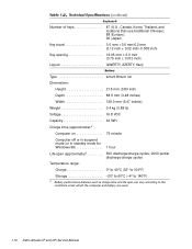
.../charge cycles Temperature range: Charge 0° to 40°C (32° to 104°F) Storage 20° to 60°C (-4° to 140°F) 3 Battery performance features such as charge time and life span can vary according to the conditions under which the computer and battery are used. 1-12 Dell Latitude CP and CPi Service Manual
.../charge cycles Temperature range: Charge 0° to 40°C (32° to 104°F) Storage 20° to 60°C (-4° to 140°F) 3 Battery performance features such as charge time and life span can vary according to the conditions under which the computer and battery are used. 1-12 Dell Latitude CP and CPi Service Manual
Service Manual
Page 20
... drive in the modular bay, and one memory module. Your computer might weigh more or less, depending on its configuration. 7 Measured with a hard-disk drive, a battery in the battery bay, a diskette drive in head-parked position. 1-14 Dell Latitude CP and CPi Service Manual
... drive in the modular bay, and one memory module. Your computer might weigh more or less, depending on its configuration. 7 Measured with a hard-disk drive, a battery in the battery bay, a diskette drive in head-parked position. 1-14 Dell Latitude CP and CPi Service Manual
Service Manual
Page 22
... peripherals, including making any necessary corrections. A temporary battery failure has occurred. Battery indicator is amber and blinking rapidly when the power switch is pressed or the AC adapter is connected to -disk mode. 2-2 Dell Latitude CP and CPi Service Manual The computer is in suspend (or standby...already turned off the computer, and then remove the battery or batteries from the system. An error occurred during system POST. Power indicator is alternating between green and amber. Battery indicator is either off . Battery indicator is off or in the power-on or ...
... peripherals, including making any necessary corrections. A temporary battery failure has occurred. Battery indicator is amber and blinking rapidly when the power switch is pressed or the AC adapter is connected to -disk mode. 2-2 Dell Latitude CP and CPi Service Manual The computer is in suspend (or standby...already turned off the computer, and then remove the battery or batteries from the system. An error occurred during system POST. Power indicator is alternating between green and amber. Battery indicator is either off . Battery indicator is off or in the power-on or ...
Service Manual
Page 30
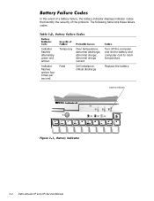
critical discharge Turn off the computer and let the battery and computer cool to room temperature. Replace the battery. The following table lists these failure codes. abnormal charge current Fatal Cell imbalance; battery indicator 3-4 Dell Latitude CP and CPi Service Manual Indicator flashes amber four times per second. abnormal charge; Temporary Over temperature; In the event of a battery failure, the battery indicator displays indicator codes that identify the severity of the problem. abnormal discharge; Indicator flashes alternately green and amber.
critical discharge Turn off the computer and let the battery and computer cool to room temperature. Replace the battery. The following table lists these failure codes. abnormal charge current Fatal Cell imbalance; battery indicator 3-4 Dell Latitude CP and CPi Service Manual Indicator flashes amber four times per second. abnormal charge; Temporary Over temperature; In the event of a battery failure, the battery indicator displays indicator codes that identify the severity of the problem. abnormal discharge; Indicator flashes alternately green and amber.
Service Manual
Page 50
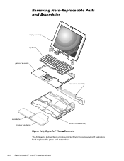
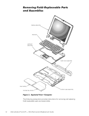
display assembly keyboard palmrest assembly back cover assembly main battery modular bay device bottom case assembly The following subsections provide instructions for removing and replacing field-replaceable parts and assemblies. 4-14 Dell Latitude CP and CPi Service Manual
display assembly keyboard palmrest assembly back cover assembly main battery modular bay device bottom case assembly The following subsections provide instructions for removing and replacing field-replaceable parts and assemblies. 4-14 Dell Latitude CP and CPi Service Manual
Service Manual
Page 76
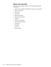
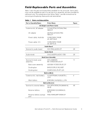
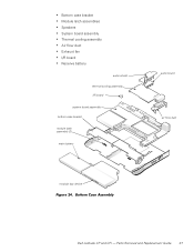
The bottom case assembly consists of the following field-replaceable components: Diskette drive assembly, CD-ROM drive assembly, or travel module Back cover assembly Audio shield Audio board Bottom case bracket Module latch assemblies Speakers System board assembly Thermal cooling assembly Air flow duct Exhaust fan I/R board Reserve battery 4-40 Dell Latitude CP and CPi Service Manual
The bottom case assembly consists of the following field-replaceable components: Diskette drive assembly, CD-ROM drive assembly, or travel module Back cover assembly Audio shield Audio board Bottom case bracket Module latch assemblies Speakers System board assembly Thermal cooling assembly Air flow duct Exhaust fan I/R board Reserve battery 4-40 Dell Latitude CP and CPi Service Manual
Service Manual
Page 78
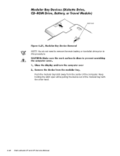
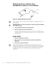
Keep holding the latch open while pulling the device out of the computer. latch lock NOTE: You do not need to remove the main battery or hard-disk drive prior to this procedure. Push the modular bay latch away from the center of the modular bay with the other hand. 4-42 Dell Latitude CP and CPi Service Manual
Keep holding the latch open while pulling the device out of the computer. latch lock NOTE: You do not need to remove the main battery or hard-disk drive prior to this procedure. Push the modular bay latch away from the center of the modular bay with the other hand. 4-42 Dell Latitude CP and CPi Service Manual
Service Manual
Page 88
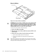
Tear the reserve battery free from the system board assembly. NOTE: When replacing the reserve battery, first connect the reserve battery cable to the system board. Then position the reserve battery on the hard-disk drive bay so there is minimal slack in the cable. 4-52 Dell Latitude CP and CPi Service Manual reserve battery reserve battery cable connector (JBAT1) To remove the reserve battery, follow these steps: a. Remove the remnants of the foam pad from the foam pad. b.
Tear the reserve battery free from the system board assembly. NOTE: When replacing the reserve battery, first connect the reserve battery cable to the system board. Then position the reserve battery on the hard-disk drive bay so there is minimal slack in the cable. 4-52 Dell Latitude CP and CPi Service Manual reserve battery reserve battery cable connector (JBAT1) To remove the reserve battery, follow these steps: a. Remove the remnants of the foam pad from the foam pad. b.
Service Manual
Page 90
..., 1-6 keyboard assembly removal, 4-18 keyboard indicators, 1-5 LCD display hinge removal, 4-38 LCD inverter board removal, 4-35, 4-36 2 Dell Latitude CP and CPi Service Manual LCD panel removal, 4-31, 4-32 LEDs, 1-4 low-battery warnings, 1-4 main battery assembly removal, 4-3 memory module removal, 4-17 memory module cover removal, 4-16 messages, system error about, 3-5 list of, 3-5 modular ... removal, 4-46 palmrest assembly removal, 4-21 POST error codes about, 3-1 list of, 3-2 power button removal, 4-24 power indicator, 1-4 power states, 1-5 precautions, 4-2 reserve battery removal, 4-52
..., 1-6 keyboard assembly removal, 4-18 keyboard indicators, 1-5 LCD display hinge removal, 4-38 LCD inverter board removal, 4-35, 4-36 2 Dell Latitude CP and CPi Service Manual LCD panel removal, 4-31, 4-32 LEDs, 1-4 low-battery warnings, 1-4 main battery assembly removal, 4-3 memory module removal, 4-17 memory module cover removal, 4-16 messages, system error about, 3-5 list of, 3-5 modular ... removal, 4-46 palmrest assembly removal, 4-21 POST error codes about, 3-1 list of, 3-2 power button removal, 4-24 power indicator, 1-4 power states, 1-5 precautions, 4-2 reserve battery removal, 4-52
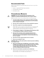
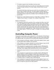
Replacement Instructions
Page 8
...Turn off and not in a C/Port Advanced Port Replicator (APR) or C/Dock Expansion Station, undock the computer. 5. Remove the main battery assembly from the computer. 7. Most of the procedures in the modular bay. If you start to -disk mode. Disconnect all open application... Disconnect the computer and any telephone or telecommunications lines from the center of the computer. Slide the battery bay latch away from ESD, periodically ground yourself by touching the metal surface of the battery bay (see Figure 2). 2 Dell Latitude CP and CPi - Save any installed PC Cards. 8.
...Turn off and not in a C/Port Advanced Port Replicator (APR) or C/Dock Expansion Station, undock the computer. 5. Remove the main battery assembly from the computer. 7. Most of the procedures in the modular bay. If you start to -disk mode. Disconnect all open application... Disconnect the computer and any telephone or telecommunications lines from the center of the computer. Slide the battery bay latch away from ESD, periodically ground yourself by touching the metal surface of the battery bay (see Figure 2). 2 Dell Latitude CP and CPi - Save any installed PC Cards. 8.
Replacement Instructions
Page 9
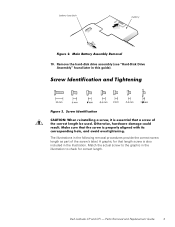
Match the actual screw to check for that length screw is also included in this guide). Parts Removal and Replacement Guide 3 The illustrations in the illustration to the graphic in the following removal procedures provide the correct screw length as part of the screw's label. Remove the hard-disk drive assembly (see "Hard-Disk Drive Assembly" found later in the illustration. A graphic for correct length. Dell Latitude CP and CPi - battery bay latch battery 10.
Match the actual screw to check for that length screw is also included in this guide). Parts Removal and Replacement Guide 3 The illustrations in the illustration to the graphic in the following removal procedures provide the correct screw length as part of the screw's label. Remove the hard-disk drive assembly (see "Hard-Disk Drive Assembly" found later in the illustration. A graphic for correct length. Dell Latitude CP and CPi - battery bay latch battery 10.
Replacement Instructions
Page 11
...cover SVC,SUBASSY, 11 assembly BK CVR/DOOR,I/O,CP Back cover assembly ASSY,BK PLT/DOOR,I/O,CP Docking bar BAR,DOOR,DCKG,MET Docking door DOOR,DCKG,PLSTC,I/O Customer kit, main battery CUS,BTRY,MN,14.4V,8CELL, 2 LITH Main battery BTRY,MN,14.4V,8CELL,LITH Service kit..., reserve battery SVC,BTRY,RSRV,7.2V,30MAH,6, 35 NIHD Reserve battery BTRY,RSRV,7.2V,30MAH,6, NIHD Reserve battery sponge PAD,FOAM,BRTY,RSRV,CP pad Dell Latitude CP and CPi - Parts Removal and ...
...cover SVC,SUBASSY, 11 assembly BK CVR/DOOR,I/O,CP Back cover assembly ASSY,BK PLT/DOOR,I/O,CP Docking bar BAR,DOOR,DCKG,MET Docking door DOOR,DCKG,PLSTC,I/O Customer kit, main battery CUS,BTRY,MN,14.4V,8CELL, 2 LITH Main battery BTRY,MN,14.4V,8CELL,LITH Service kit..., reserve battery SVC,BTRY,RSRV,7.2V,30MAH,6, 35 NIHD Reserve battery BTRY,RSRV,7.2V,30MAH,6, NIHD Reserve battery sponge PAD,FOAM,BRTY,RSRV,CP pad Dell Latitude CP and CPi - Parts Removal and ...

Replacement Instructions
Page 19
...Reserve battery Foam pad ASSY,PRM/PWA,ENGINE, CPixxx* SUBASSY,PWA/ENGINE,CP PWA,FAST IR,CP GRMT,RBR,BOOT,MCPHN PWA,PLN,0M,NB,CP PWA,DTRBD,VID/PCMCIA,CP PWA,LED,CP SHLD,BTM,PLN ASSY,CP SHLD,TOP,1ST,PLN ASSY,CP SHLD,TOP,2ND,PLN ASSY,CP FAN,25X25X10,CP MCPHN,CP ...BTRY,RSRV,7.2,30MAH,6,NIHD PAD,FOAM,BTRY,RSRV,CP Service kit, thermal cooling SVC,SUBASSY,HTSNK, 30 subassembly CPU,HYB,CP Touch-pad service kit SVC,TPAD,SQ,INTFC,CP 13 Touch-pad subassembly TPA,INTFC,CP * Substitute the drive capacity for xxxxx, the drive height for yy, and the manufacturer for zzz. Dell Latitude CP and CPi...
...Reserve battery Foam pad ASSY,PRM/PWA,ENGINE, CPixxx* SUBASSY,PWA/ENGINE,CP PWA,FAST IR,CP GRMT,RBR,BOOT,MCPHN PWA,PLN,0M,NB,CP PWA,DTRBD,VID/PCMCIA,CP PWA,LED,CP SHLD,BTM,PLN ASSY,CP SHLD,TOP,1ST,PLN ASSY,CP SHLD,TOP,2ND,PLN ASSY,CP FAN,25X25X10,CP MCPHN,CP ...BTRY,RSRV,7.2,30MAH,6,NIHD PAD,FOAM,BTRY,RSRV,CP Service kit, thermal cooling SVC,SUBASSY,HTSNK, 30 subassembly CPU,HYB,CP Touch-pad service kit SVC,TPAD,SQ,INTFC,CP 13 Touch-pad subassembly TPA,INTFC,CP * Substitute the drive capacity for xxxxx, the drive height for yy, and the manufacturer for zzz. Dell Latitude CP and CPi...
Replacement Instructions
Page 20
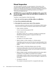
Parts Removal and Replacement Guide display assembly keyboard palmrest assembly back cover assembly main battery modular bay device bottom case assembly The following subsections provide instructions for removing and replacing field-replaceable parts and assemblies. 14 Dell Latitude CP and CPi -
Parts Removal and Replacement Guide display assembly keyboard palmrest assembly back cover assembly main battery modular bay device bottom case assembly The following subsections provide instructions for removing and replacing field-replaceable parts and assemblies. 14 Dell Latitude CP and CPi -
Replacement Instructions
Page 43
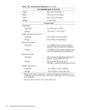
Parts Removal and Replacement Guide 37 Bottom case bracket Module latch assemblies Speakers System board assembly Thermal cooling assembly Air flow duct Exhaust fan I/R board Reserve battery audio shield thermal cooling assembly I/R board system board assembly bottom case bracket module latch assembly (2) main battery audio board air flow duct modular bay device Dell Latitude CP and CPi -
Parts Removal and Replacement Guide 37 Bottom case bracket Module latch assemblies Speakers System board assembly Thermal cooling assembly Air flow duct Exhaust fan I/R board Reserve battery audio shield thermal cooling assembly I/R board system board assembly bottom case bracket module latch assembly (2) main battery audio board air flow duct modular bay device Dell Latitude CP and CPi -
Replacement Instructions
Page 44
... battery or hard-disk drive prior to this by temporarily installing a device in the modular bay. (You can check this procedure. 1. Remove the audio board shield. Remove the device from the center of the modular bay with devices installed in the modular bay prior to reinstalling the palmrest assembly.) 38 Dell Latitude CP and CPi...
... battery or hard-disk drive prior to this by temporarily installing a device in the modular bay. (You can check this procedure. 1. Remove the audio board shield. Remove the device from the center of the modular bay with devices installed in the modular bay prior to reinstalling the palmrest assembly.) 38 Dell Latitude CP and CPi...


