Service Manual
Page 6
... 3 9 Palmrest Assembly 4 0 Removing the Palmrest Assembly 4 1 Reserve Battery 4 2 Removing the Reserve Battery 4 3 Replacing the Reserve Battery 4 4 System Board Assembly 4 4 Removing the System Board 4 6 Battery and Modular Bay Latch Assemblies 4 7 Removing and Replacing the Battery and Modular Bay Latch Assemblies 4 8 Battery Charger Board 4 9 Removing the Battery Charger Board 5 0 Replacing the Battery Charger Board 5 0 LED Board 5 1 Removing the LED Board...
... 3 9 Palmrest Assembly 4 0 Removing the Palmrest Assembly 4 1 Reserve Battery 4 2 Removing the Reserve Battery 4 3 Replacing the Reserve Battery 4 4 System Board Assembly 4 4 Removing the System Board 4 6 Battery and Modular Bay Latch Assemblies 4 7 Removing and Replacing the Battery and Modular Bay Latch Assemblies 4 8 Battery Charger Board 4 9 Removing the Battery Charger Board 5 0 Replacing the Battery Charger Board 5 0 LED Board 5 1 Removing the LED Board...
Service Manual
Page 10
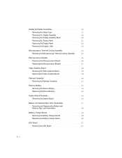
... damaging the computer, perform the following steps before you service the computer. 11 Remove any installed PC Cards or plastic blanks from the battery bay. Damage due to Work Inside the Computer NOTICE: Only a certified service technician should perform repairs on the computer chassis. 13 Handle ... you begin working inside the computer. 1 Make sure that is not authorized by Dell is flat and clean to 20 seconds and then disconnect any installed batteries before you work surface. 10 Remove the battery from the PC Card slot. 9 Close the display and turn the computer upside ...
... damaging the computer, perform the following steps before you service the computer. 11 Remove any installed PC Cards or plastic blanks from the battery bay. Damage due to Work Inside the Computer NOTICE: Only a certified service technician should perform repairs on the computer chassis. 13 Handle ... you begin working inside the computer. 1 Make sure that is not authorized by Dell is flat and clean to 20 seconds and then disconnect any installed batteries before you work surface. 10 Remove the battery from the PC Card slot. 9 Close the display and turn the computer upside ...
Service Manual
Page 15
SECTION 2 Removing and Replacing Parts System Components Hard Drive Fixed Optical Drive Memory Module Mini PCI Card Assembly Keyboard Assembly Display and Bezel Assemblies Microprocessor Thermal Cooling Assembly Microprocessor Module Video Graphics Board Palmrest Assembly Reserve Battery System Board Assembly Battery and Modular Bay Latch Assemblies Battery Charger Board LED Board Fan Assembly RJ-11/RJ-45 Board www.dell.com | support.dell.com 2
SECTION 2 Removing and Replacing Parts System Components Hard Drive Fixed Optical Drive Memory Module Mini PCI Card Assembly Keyboard Assembly Display and Bezel Assemblies Microprocessor Thermal Cooling Assembly Microprocessor Module Video Graphics Board Palmrest Assembly Reserve Battery System Board Assembly Battery and Modular Bay Latch Assemblies Battery Charger Board LED Board Fan Assembly RJ-11/RJ-45 Board www.dell.com | support.dell.com 2

Service Manual
Page 16
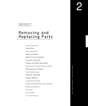
d ell. com System Components Exploded View display assembly keyboard palmrest assembly hinge cover fixed optical drive modular device thermal cooling assembly system board hard drive 14 Rem o vi n g an d Rep l a ci n g Pa rt s bottom case assembly main battery w w w.d el l.co m | su p po rt.
d ell. com System Components Exploded View display assembly keyboard palmrest assembly hinge cover fixed optical drive modular device thermal cooling assembly system board hard drive 14 Rem o vi n g an d Rep l a ci n g Pa rt s bottom case assembly main battery w w w.d el l.co m | su p po rt.

Service Manual
Page 17
Hard Drive NOTICE: Disconnect the computer and attached devices from the electrical outlet and remove any installed batteries. Damage due to shock. NOTICE: Unless otherwise noted, each procedure in this manual assumes that is not authorized by Dell is very sensitive to servicing that a part can be replaced by your computer. NOTICE: To...
Hard Drive NOTICE: Disconnect the computer and attached devices from the electrical outlet and remove any installed batteries. Damage due to shock. NOTICE: Unless otherwise noted, each procedure in this manual assumes that is not authorized by Dell is very sensitive to servicing that a part can be replaced by your computer. NOTICE: To...

Service Manual
Page 18
... the computer. w w w.d el l.co m | su p po rt. Fixed Optical Drive NOTICE: Disconnect the computer and attached devices from the electrical outlet and remove any installed batteries. com Removing the Hard Drive 1 Follow the instructions in the hard drive door. Replacing the Hard Drive 1 Gently push the hard drive into place. 3 Replace...
... the computer. w w w.d el l.co m | su p po rt. Fixed Optical Drive NOTICE: Disconnect the computer and attached devices from the electrical outlet and remove any installed batteries. com Removing the Hard Drive 1 Follow the instructions in the hard drive door. Replacing the Hard Drive 1 Gently push the hard drive into place. 3 Replace...
Service Manual
Page 19
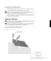
... use the pull tab to Work Inside the Computer." 2 Loosen the captive screw on the computer. Memory Module NOTICE: Disconnect the computer and any installed batteries.
... use the pull tab to Work Inside the Computer." 2 Loosen the captive screw on the computer. Memory Module NOTICE: Disconnect the computer and any installed batteries.
Service Manual
Page 21
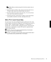
... Card Assembly You must be connected to the system's internal antenna. NOTICE: Disconnect the computer and attached devices from electrical outlets and remove any installed batteries. NOTICE: To avoid ESD, ground yourself by using a wrist grounding strap or by periodically touching unpainted metal on the memory module cover into place. NOTE...
... Card Assembly You must be connected to the system's internal antenna. NOTICE: Disconnect the computer and attached devices from electrical outlets and remove any installed batteries. NOTICE: To avoid ESD, ground yourself by using a wrist grounding strap or by periodically touching unpainted metal on the memory module cover into place. NOTE...

Service Manual
Page 24
Keyboard Assembly NOTICE: Disconnect the computer and attached devices from electrical outlets and remove any installed batteries. com Mini-PCI Wireless NIC Assembly Using Antenna Cable connection to internal system antenna mini-coax antenna cable wiring harness outermost antenna connector on card ...
Keyboard Assembly NOTICE: Disconnect the computer and attached devices from electrical outlets and remove any installed batteries. com Mini-PCI Wireless NIC Assembly Using Antenna Cable connection to internal system antenna mini-coax antenna cable wiring harness outermost antenna connector on card ...

Service Manual
Page 28
Display Assembly display display flex cable hinge cover bottom case assembly 26 Rem o vi n g an d Rep l a ci n g Pa rt s 6-mm screws (3) d ell. com Display and Bezel Assemblies NOTICE: Disconnect the computer and attached devices from electrical outlets and remove any installed batteries. NOTICE: To avoid ESD, ground yourself by using a wrist grounding strap or by periodically touching unpainted metal on the computer. w w w.d el l.co m | su p po rt.
Display Assembly display display flex cable hinge cover bottom case assembly 26 Rem o vi n g an d Rep l a ci n g Pa rt s 6-mm screws (3) d ell. com Display and Bezel Assemblies NOTICE: Disconnect the computer and attached devices from electrical outlets and remove any installed batteries. NOTICE: To avoid ESD, ground yourself by using a wrist grounding strap or by periodically touching unpainted metal on the computer. w w w.d el l.co m | su p po rt.

Service Manual
Page 36
... touching unpainted metal on the computer. com Microprocessor Thermal Cooling Assembly NOTICE: Disconnect the computer and attached devices from electrical outlets and remove any installed batteries.
... touching unpainted metal on the computer. com Microprocessor Thermal Cooling Assembly NOTICE: Disconnect the computer and attached devices from electrical outlets and remove any installed batteries.

Service Manual
Page 37
... the heat transfer capability of the microprocessor retaining clip. Microprocessor Module NOTICE: Disconnect the computer and attached devices from electrical outlets and remove any installed batteries. Re m ov i n g a nd Re p l ac i n g Pa rt s 35 NOTICE: To avoid ESD, ground yourself by using a wrist grounding strap or by pivoting the top of...
... the heat transfer capability of the microprocessor retaining clip. Microprocessor Module NOTICE: Disconnect the computer and attached devices from electrical outlets and remove any installed batteries. Re m ov i n g a nd Re p l ac i n g Pa rt s 35 NOTICE: To avoid ESD, ground yourself by using a wrist grounding strap or by pivoting the top of...

Service Manual
Page 40
... retaining clip, insert a flat-blade screwdriver into the latch mechanism and pivot the top of the screwdriver away from electrical outlets and remove any installed batteries. 38 Rem o vi n g an d Rep l a ci n g Pa rt s
... retaining clip, insert a flat-blade screwdriver into the latch mechanism and pivot the top of the screwdriver away from electrical outlets and remove any installed batteries. 38 Rem o vi n g an d Rep l a ci n g Pa rt s

Service Manual
Page 42
...unpainted metal on the computer. d ell. com NOTICE: Make sure the board is turned off. Palmrest Assembly pull loop NOTICE: The reserve battery provides power to the computer's time RTC and NVRAM when the computer is correctly and firmly seated before you disconnect the reserve... battery. 40 Rem o vi n g an d Rep l a ci n g Pa rt s Removing the palmrest disconnects the reserve battery and causes the computer to do so will cause intermittent video failures. 2 Replace the three screws....
...unpainted metal on the computer. d ell. com NOTICE: Make sure the board is turned off. Palmrest Assembly pull loop NOTICE: The reserve battery provides power to the computer's time RTC and NVRAM when the computer is correctly and firmly seated before you disconnect the reserve... battery. 40 Rem o vi n g an d Rep l a ci n g Pa rt s Removing the palmrest disconnects the reserve battery and causes the computer to do so will cause intermittent video failures. 2 Replace the three screws....

Service Manual
Page 44
... the computer to disconnect the palmrest flex cable from electrical outlets and remove any installed batteries. com 8 Turn the computer over. 9 Use the pull loop to lose the date and time information as well as all user-specified ...periodically touching unpainted metal on the system board. 10 Carefully lift out the palmrest assembly. d ell. pad connector on the computer. Reserve Battery reserve battery cable reserve battery palmrest bracket NOTICE: The reserve battery provides power to the computer's RTC and NVRAM when the computer is turned off. w w w.d el l.co m | su p ...
... the computer to disconnect the palmrest flex cable from electrical outlets and remove any installed batteries. com 8 Turn the computer over. 9 Use the pull loop to lose the date and time information as well as all user-specified ...periodically touching unpainted metal on the system board. 10 Carefully lift out the palmrest assembly. d ell. pad connector on the computer. Reserve Battery reserve battery cable reserve battery palmrest bracket NOTICE: The reserve battery provides power to the computer's RTC and NVRAM when the computer is turned off. w w w.d el l.co m | su p ...

Service Manual
Page 45
...palmrest bracket. 8 While supporting the palmrest flex cable, lift out the palmrest bracket and turn it over. 9 Disconnect the reserve battery cable. 10 Remove the reserve battery: a Pry the reserve battery free from the palmrest bracket. b Remove the foam-pad remnants from the metal palmrest bracket. Removing the Reserve... Battery 1 Follow the instructions in "Preparing to Work Inside the Computer." 2 Remove the keyboard. 3 Remove the hinge cover. 4 Remove the display assembly. 5 ...
...palmrest bracket. 8 While supporting the palmrest flex cable, lift out the palmrest bracket and turn it over. 9 Disconnect the reserve battery cable. 10 Remove the reserve battery: a Pry the reserve battery free from the palmrest bracket. b Remove the foam-pad remnants from the metal palmrest bracket. Removing the Reserve... Battery 1 Follow the instructions in "Preparing to Work Inside the Computer." 2 Remove the keyboard. 3 Remove the hinge cover. 4 Remove the display assembly. 5 ...

Service Manual
Page 46
... Assembly NOTICE: Disconnect the computer and attached devices from electrical outlets and remove any installed batteries. w w w.d el l.co m | su p po rt. com Replacing the Reserve Battery 1 Seat the reserve battery and press it into place. 2 Connect the reserve battery cable. 3 Place the palmrest bracket loosely in the palmrest, and connect the palmrest flex cable...
... Assembly NOTICE: Disconnect the computer and attached devices from electrical outlets and remove any installed batteries. w w w.d el l.co m | su p po rt. com Replacing the Reserve Battery 1 Seat the reserve battery and press it into place. 2 Connect the reserve battery cable. 3 Place the palmrest bracket loosely in the palmrest, and connect the palmrest flex cable...

Service Manual
Page 49
Re m ov i n g a nd Re p l ac i n g Pa rt s 47 System Board Battery and Modular Bay Latch Assemblies NOTICE: Disconnect the computer and attached devices from electrical outlets and remove any installed batteries. NOTICE: To avoid ESD, ground yourself by using a wrist grounding strap or by periodically touching unpainted metal on the computer.
Re m ov i n g a nd Re p l ac i n g Pa rt s 47 System Board Battery and Modular Bay Latch Assemblies NOTICE: Disconnect the computer and attached devices from electrical outlets and remove any installed batteries. NOTICE: To avoid ESD, ground yourself by using a wrist grounding strap or by periodically touching unpainted metal on the computer.

Service Manual
Page 50
com Battery and Modular Bay L atch Assemblies wear ribs (2 on underside) bumps slider spring location of snap tabs (2) latch buttons (2) bottom case assembly Removing and Replacing the Battery and Modular Bay Latch Assemblies 1 Follow the instructions in "Preparing to Work Inside the Computer." 2 Remove the keyboard. 3 Remove the hinge cover. 4 Remove the display assembly. 5 Remove the palmrest assembly. 48 Rem o vi n g an d Rep l a ci n g Pa rt s d ell. w w w.d el l.co m | su p po rt.
com Battery and Modular Bay L atch Assemblies wear ribs (2 on underside) bumps slider spring location of snap tabs (2) latch buttons (2) bottom case assembly Removing and Replacing the Battery and Modular Bay Latch Assemblies 1 Follow the instructions in "Preparing to Work Inside the Computer." 2 Remove the keyboard. 3 Remove the hinge cover. 4 Remove the display assembly. 5 Remove the palmrest assembly. 48 Rem o vi n g an d Rep l a ci n g Pa rt s d ell. w w w.d el l.co m | su p po rt.

Service Manual
Page 51
... from the bottom of the case without loosening the upper latch assembly (spring and slider). 6 Remove a latch button from electrical outlets and remove any installed batteries. Battery Charger Board NOTICE: Disconnect the computer and attached devices from the bottom case assembly by periodically touching unpainted metal on the inside of the latch.
... from the bottom of the case without loosening the upper latch assembly (spring and slider). 6 Remove a latch button from electrical outlets and remove any installed batteries. Battery Charger Board NOTICE: Disconnect the computer and attached devices from the bottom case assembly by periodically touching unpainted metal on the inside of the latch.

