Service Manual
Page 5
... System Components 1 4 Hard Drive 1 5 Removing the Hard Drive 1 6 Replacing the Hard Drive 1 6 Fixed Optical Drive 1 6 Removing the Fixed Optical Drive 1 7 Memory Module 1 7 Removing the Memory Module Cover 1 7 Removing the Memory Modules 1 8 Replacing the Memory Modules 1 8 Mini PCI Card Assembly 1 9 Removing the Mini PCI Card Assembly 2 0 Replacing the Mini PCI Card Assembly 2 1 Keyboard Assembly 2 2 Removing...
... System Components 1 4 Hard Drive 1 5 Removing the Hard Drive 1 6 Replacing the Hard Drive 1 6 Fixed Optical Drive 1 6 Removing the Fixed Optical Drive 1 7 Memory Module 1 7 Removing the Memory Module Cover 1 7 Removing the Memory Modules 1 8 Replacing the Memory Modules 1 8 Mini PCI Card Assembly 1 9 Removing the Mini PCI Card Assembly 2 0 Replacing the Mini PCI Card Assembly 2 1 Keyboard Assembly 2 2 Removing...

Service Manual
Page 13
one in memory door and one in miniPCI door) Display to Base: M2.5 x 6 mm (3 each; 2 at back of system; 1 at flex cable strain relief) Display Bezel: Rubber screw ...
one in memory door and one in miniPCI door) Display to Base: M2.5 x 6 mm (3 each; 2 at back of system; 1 at flex cable strain relief) Display Bezel: Rubber screw ...
Service Manual
Page 15
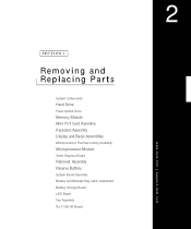
SECTION 2 Removing and Replacing Parts System Components Hard Drive Fixed Optical Drive Memory Module Mini PCI Card Assembly Keyboard Assembly Display and Bezel Assemblies Microprocessor Thermal Cooling Assembly Microprocessor Module Video Graphics Board Palmrest Assembly Reserve Battery System Board Assembly Battery and Modular Bay Latch Assemblies Battery Charger Board LED Board Fan Assembly RJ-11/RJ-45 Board www.dell.com | support.dell.com 2
SECTION 2 Removing and Replacing Parts System Components Hard Drive Fixed Optical Drive Memory Module Mini PCI Card Assembly Keyboard Assembly Display and Bezel Assemblies Microprocessor Thermal Cooling Assembly Microprocessor Module Video Graphics Board Palmrest Assembly Reserve Battery System Board Assembly Battery and Modular Bay Latch Assemblies Battery Charger Board LED Board Fan Assembly RJ-11/RJ-45 Board www.dell.com | support.dell.com 2
Service Manual
Page 19
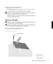
... Cover 20-mm screw Re m ov i n g a nd Re p l ac i n g Pa rt s 17 Memory Module NOTICE: Disconnect the computer and any installed batteries. NOTICE: To keep the pull tab from electrical outlets and remove any attached devices from catching ...
... Cover 20-mm screw Re m ov i n g a nd Re p l ac i n g Pa rt s 17 Memory Module NOTICE: Disconnect the computer and any installed batteries. NOTICE: To keep the pull tab from electrical outlets and remove any attached devices from catching ...
Service Manual
Page 20
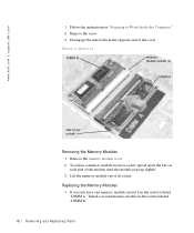
w w w.d el l.co m | su p po rt. Install a second memory module in the socket labeled "DIMM A." Replacing the Memory Modules 1 If you only have one memory module, install it in the socket labeled "DIMM B." 18 Rem o vi n g an d Rep l a ci n g Pa rt s d ell. com 1 Follow ... spread apart the tabs at each side of the module until the module pops up slightly. 3 Lift the memory module out of the cover. Memory Modules DIMM B memory module sockets (2) DIMM A tabs (2 per socket) Removing the Memory Modules 1 Remove the memory module cover. 2 To release a memory module from its socket.
w w w.d el l.co m | su p po rt. Install a second memory module in the socket labeled "DIMM A." Replacing the Memory Modules 1 If you only have one memory module, install it in the socket labeled "DIMM B." 18 Rem o vi n g an d Rep l a ci n g Pa rt s d ell. com 1 Follow ... spread apart the tabs at each side of the module until the module pops up slightly. 3 Lift the memory module out of the cover. Memory Modules DIMM B memory module sockets (2) DIMM A tabs (2 per socket) Removing the Memory Modules 1 Remove the memory module cover. 2 To release a memory module from its socket.
Service Manual
Page 21
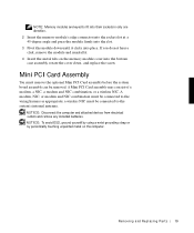
... to the wiring harness as appropriate; Re m ov i n g a nd Re p l ac i n g Pa rt s 19 NOTE: Memory modules are keyed to fit into their sockets in only one direction. 2 Insert the memory module's edge connector into the socket slot at a 45-degree angle and press the module firmly into place...and remove any installed batteries. NOTICE: To avoid ESD, ground yourself by using a wrist grounding strap or by periodically touching unpainted metal on the memory module cover into the bottom case assembly, rotate the cover down until it clicks into the slot. 3 Pivot the module down , and replace ...
... to the wiring harness as appropriate; Re m ov i n g a nd Re p l ac i n g Pa rt s 19 NOTE: Memory modules are keyed to fit into their sockets in only one direction. 2 Insert the memory module's edge connector into the socket slot at a 45-degree angle and press the module firmly into place...and remove any installed batteries. NOTICE: To avoid ESD, ground yourself by using a wrist grounding strap or by periodically touching unpainted metal on the memory module cover into the bottom case assembly, rotate the cover down until it clicks into the slot. 3 Pivot the module down , and replace ...

Service Manual
Page 48
For instructions on updating or reflashing the BIOS, see the Dell Portable Computer BIOS Update Guide. d ell. Removing the System Board 1 Follow the instructions in "Preparing to the replacement system board assembly. com The replacement kit... number to Work Inside the Computer." 2 Remove the hard drive and the fixed optical drive. 3 Remove any installed Mini PCI Cards. 4 If migrating the memory, remove all installed memory modules. 5 Remove the keyboard. 6 Remove the hinge cover. 7 Remove the display assembly. 8 Remove the palmrest assembly. 9 Remove the video graphics board. 10 Remove...
For instructions on updating or reflashing the BIOS, see the Dell Portable Computer BIOS Update Guide. d ell. Removing the System Board 1 Follow the instructions in "Preparing to the replacement system board assembly. com The replacement kit... number to Work Inside the Computer." 2 Remove the hard drive and the fixed optical drive. 3 Remove any installed Mini PCI Cards. 4 If migrating the memory, remove all installed memory modules. 5 Remove the keyboard. 6 Remove the hinge cover. 7 Remove the display assembly. 8 Remove the palmrest assembly. 9 Remove the video graphics board. 10 Remove...

Service Manual
Page 59
... card assembly removing, 20 replacing, 21 K keyboard assembly removing, 23 replacing, 25 L latch assemblies, battery and modular bay, 47 LED board removing, 51 replacing, 52 M memory module removing modules, 1 8 removing the cover, 1 7 replacing modules, 18 microprocessor module removing, 36 replacing, 37 P palmrest assembly, 40 palmrest flex cable, 43 preparing to work...
... card assembly removing, 20 replacing, 21 K keyboard assembly removing, 23 replacing, 25 L latch assemblies, battery and modular bay, 47 LED board removing, 51 replacing, 52 M memory module removing modules, 1 8 removing the cover, 1 7 replacing modules, 18 microprocessor module removing, 36 replacing, 37 P palmrest assembly, 40 palmrest flex cable, 43 preparing to work...
System Information Guide
Page 6
... contact you local waste disposal agency for personal injury or shock. • If the computer is when you are installing memory modules. They may contain flammable substances. Preparing to Work Inside Your Computer Observe the following safety guidelines when working inside of... potential for disposal instructions. • Clean your computer with a soft cloth dampened with water rather than with household waste. support.dell.com Dell Latitude System Information 1-3 Discard used with the modem should ever access the inside your computer. NOTICE: The only time you should be ...
... contact you local waste disposal agency for personal injury or shock. • If the computer is when you are installing memory modules. They may contain flammable substances. Preparing to Work Inside Your Computer Observe the following safety guidelines when working inside of... potential for disposal instructions. • Clean your computer with a soft cloth dampened with water rather than with household waste. support.dell.com Dell Latitude System Information 1-3 Discard used with the modem should ever access the inside your computer. NOTICE: The only time you should be ...

System Information Guide
Page 7
... the appropriate EMC classification for the intended environment. Additional regulatory information regarding EMI. You can do so by Dell could void your authority to comply with applicable regulations regarding your computer can harm electronic components inside your computer...., such as a memory module. To prevent static damage, discharge static electricity from Dell. General EMC Guidelines • Shielded signal cables: Using shielded cables ensures that you touch any signal or emission, radiated in your online User's Guide. 1-4 Dell Latitude System Information For parallel...
... the appropriate EMC classification for the intended environment. Additional regulatory information regarding EMI. You can do so by Dell could void your authority to comply with applicable regulations regarding your computer can harm electronic components inside your computer...., such as a memory module. To prevent static damage, discharge static electricity from Dell. General EMC Guidelines • Shielded signal cables: Using shielded cables ensures that you touch any signal or emission, radiated in your online User's Guide. 1-4 Dell Latitude System Information For parallel...


