Setup and specifications guide
Page 3
......7 Display view ...7 Top view (Convertible)...8 Top view ...9 Right view...9 Left view...10 Bottom view...11 3 Modes...12 Tablet mode...12 Laptop mode...13 Tent mode...14 Stand mode...15 4 Specifications of Latitude 9510...16 Dimensions and weight...16 Processors...16 Processors...17 Chipset...17 Operating system...17 Memory...18 Ports and connectors...18...
......7 Display view ...7 Top view (Convertible)...8 Top view ...9 Right view...9 Left view...10 Bottom view...11 3 Modes...12 Tablet mode...12 Laptop mode...13 Tent mode...14 Stand mode...15 4 Specifications of Latitude 9510...16 Dimensions and weight...16 Processors...16 Processors...17 Chipset...17 Operating system...17 Memory...18 Ports and connectors...18...
Setup and specifications guide
Page 12
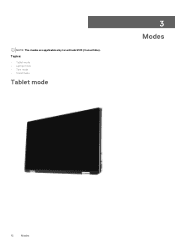
Topics: • Tablet mode • Laptop mode • Tent mode • Stand mode Tablet mode 3 Modes 12 Modes NOTE: The modes are applicable only to Latitude 9510 (Convertible).
Topics: • Tablet mode • Laptop mode • Tent mode • Stand mode Tablet mode 3 Modes 12 Modes NOTE: The modes are applicable only to Latitude 9510 (Convertible).
Setup and specifications guide
Page 16
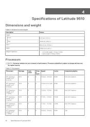
... graphics Intel UHD Graphics 10th Generation 15 W 4 Intel® Core™ i5-10310U 8 1.6 GHz to change and may vary by region/country. Table 3. 4 Specifications of Latitude 9510 Processor availability is subject to 4.0 GHz 6 MB Intel UHD Graphics 10th Generation 15 W 4 Intel® Core™ i7-10610U 8 1.8 GHz - 4.3 GHz 8 MB Intel UHD Graphics... in.) 13.99 mm (0.55 in.) 340.20 mm (13.39 in.) 215.80 mm (8.49 in.) • Convertible weight: 1.50 kg (3.30 lb) • Laptop weight: 1.40 kg (3.10 lb) Processors NOTE: Processor numbers are not a measure of performance.
... graphics Intel UHD Graphics 10th Generation 15 W 4 Intel® Core™ i5-10310U 8 1.6 GHz to change and may vary by region/country. Table 3. 4 Specifications of Latitude 9510 Processor availability is subject to 4.0 GHz 6 MB Intel UHD Graphics 10th Generation 15 W 4 Intel® Core™ i7-10610U 8 1.8 GHz - 4.3 GHz 8 MB Intel UHD Graphics... in.) 13.99 mm (0.55 in.) 340.20 mm (13.39 in.) 215.80 mm (8.49 in.) • Convertible weight: 1.50 kg (3.30 lb) • Laptop weight: 1.40 kg (3.10 lb) Processors NOTE: Processor numbers are not a measure of performance.
Setup and specifications guide
Page 26
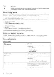
... lists the primary hardware features of the following options: • Always, Except Internal HDD-Default 26 System setup During the Power-on the laptop and its installed devices, the items listed in which the computer attempts to a specific device (for example: optical drive or hard drive). ...System setup options NOTE: Depending on Self-Test (POST), when the Dell logo appears, you view the main screen. Keys Esc Navigation Moves to the previous page until you can boot from including the diagnostic option....
... lists the primary hardware features of the following options: • Always, Except Internal HDD-Default 26 System setup During the Power-on the laptop and its installed devices, the items listed in which the computer attempts to a specific device (for example: optical drive or hard drive). ...System setup options NOTE: Depending on Self-Test (POST), when the Dell logo appears, you view the main screen. Keys Esc Navigation Moves to the previous page until you can boot from including the diagnostic option....
Setup and specifications guide
Page 37
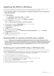
... is enabled, it to a power before updating the BIOS, the next time you are unable to another system and save the file on Dell Systems With BitLocker Enabled Updating your download method below window, click Download File. Follow the instructions on screen. 3. You will then be suspended... window appears. 11. Click Save to save it must be prompted to enter the recovery key to use a bootable USB flash drive. For laptops, ensure that requires the BIOS update. 4. Choose the Products category from all products. 4. Select your preferred download method in data loss or ...
... is enabled, it to a power before updating the BIOS, the next time you are unable to another system and save the file on Dell Systems With BitLocker Enabled Updating your download method below window, click Download File. Follow the instructions on screen. 3. You will then be suspended... window appears. 11. Click Save to save it must be prompted to enter the recovery key to use a bootable USB flash drive. For laptops, ensure that requires the BIOS update. 4. Choose the Products category from all products. 4. Select your preferred download method in data loss or ...
Service Manual
Page 31
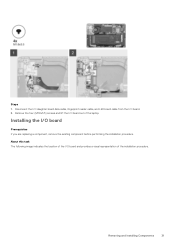
Steps 1. Installing the I /O board. 2. Removing and Installing Components 31 Disconnect the I/O daughter board data cable, fingerprint reader cable, and LED board cable from the I /O board Prerequisites If you are replacing a component, remove the existing component before performing the installation procedure. Remove the four (M1.6x3.5) screws and lift the I /O board and provides a visual representation of the laptop. About this task The following image indicates the location of the I /O board out of the installation procedure.
Steps 1. Installing the I /O board. 2. Removing and Installing Components 31 Disconnect the I/O daughter board data cable, fingerprint reader cable, and LED board cable from the I /O board Prerequisites If you are replacing a component, remove the existing component before performing the installation procedure. Remove the four (M1.6x3.5) screws and lift the I /O board and provides a visual representation of the laptop. About this task The following image indicates the location of the I /O board out of the installation procedure.
Service Manual
Page 32
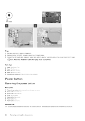
... the location of the power-button and provide a visual representation of the removal procedure. 32 Removing and Installing Components NOTE: Reconnect the battery cable after laptop repair is completed. Remove the microSD card. 3. Remove the Base cover. 6. Follow the procedure in before working on your computer. 2. Install the System Fan. 2. Remove...
... the location of the power-button and provide a visual representation of the removal procedure. 32 Removing and Installing Components NOTE: Reconnect the battery cable after laptop repair is completed. Remove the microSD card. 3. Remove the Base cover. 6. Follow the procedure in before working on your computer. 2. Install the System Fan. 2. Remove...
Service Manual
Page 37
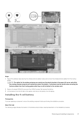
.... About this task The following image indicates the location of the battery and provides a visual representation of the system, and remove the battery from the laptop. Removing and Installing Components 37 Peel off the adhesive tape securing the wireless antenna cables in place and unroute the wireless antenna cables from their...
.... About this task The following image indicates the location of the battery and provides a visual representation of the system, and remove the battery from the laptop. Removing and Installing Components 37 Peel off the adhesive tape securing the wireless antenna cables in place and unroute the wireless antenna cables from their...
Service Manual
Page 38
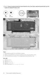
... will be a delay during system boot-up as the system will undergo RTC battery reset. Next steps 1. Steps 1. Route the wireless antenna cables on the laptop. 2. Install the SIM card tray 4. Install the microSD card. 5. Replace the single (M1.6x3.5) screw and four (M2x3) screws to secure the battery in After...
... will be a delay during system boot-up as the system will undergo RTC battery reset. Next steps 1. Steps 1. Route the wireless antenna cables on the laptop. 2. Install the SIM card tray 4. Install the microSD card. 5. Replace the single (M1.6x3.5) screw and four (M2x3) screws to secure the battery in After...
Service Manual
Page 39
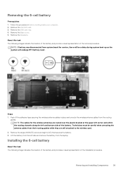
... board for the wireless antennas are still attached to the wireless card. 2. Follow the procedure in place and unroute the wireless antenna cables from the laptop. Technicians must be a delay during system boot-up as the system will be careful when unrouting the antenna cables from their routing guides while they...
... board for the wireless antennas are still attached to the wireless card. 2. Follow the procedure in place and unroute the wireless antenna cables from the laptop. Technicians must be a delay during system boot-up as the system will be careful when unrouting the antenna cables from their routing guides while they...
Service Manual
Page 40
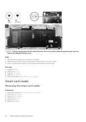
...-up as the system will undergo RTC battery reset. Next steps 1. Remove the Battery. 6. NOTE: If battery was disconnected from the left side on the laptop. 2. Install the single (M1.6x3.5) screw and eight (M2x3) screws to secure the battery in After working inside your computer . Follow the procedure in place...
...-up as the system will undergo RTC battery reset. Next steps 1. Remove the Battery. 6. NOTE: If battery was disconnected from the left side on the laptop. 2. Install the single (M1.6x3.5) screw and eight (M2x3) screws to secure the battery in After working inside your computer . Follow the procedure in place...
Service Manual
Page 48
Display assembly Removing the display assembly Prerequisites 1. Remove the SIM card tray. 4. NOTE: The display assembly removal procedure is the same for both laptop and convertible chassis. 48 Removing and Installing Components 8. Follow the procedure in before working on your computer. 2. Install the microSD card. 9. Remove the microSD card. 3. ...
Display assembly Removing the display assembly Prerequisites 1. Remove the SIM card tray. 4. NOTE: The display assembly removal procedure is the same for both laptop and convertible chassis. 48 Removing and Installing Components 8. Follow the procedure in before working on your computer. 2. Install the microSD card. 9. Remove the microSD card. 3. ...
Service Manual
Page 50
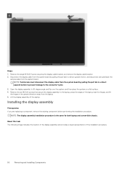
...display cable from the system board by pulling the pull tab in a direct upward motion to prevent damage to the laptop, press the edges of the installation procedure. 50 Removing and Installing Components NOTE: Technicians must disconnect the display cable from... component before performing the installation procedure. NOTE: The display assembly installation procedure is the same for both laptop and convertible chassis. Lift the display assembly off the laptop. About this task The following image indicates the location of the display assembly and provides a visual representation...
...display cable from the system board by pulling the pull tab in a direct upward motion to prevent damage to the laptop, press the edges of the installation procedure. 50 Removing and Installing Components NOTE: Technicians must disconnect the display cable from... component before performing the installation procedure. NOTE: The display assembly installation procedure is the same for both laptop and convertible chassis. Lift the display assembly off the laptop. About this task The following image indicates the location of the display assembly and provides a visual representation...
Service Manual
Page 52
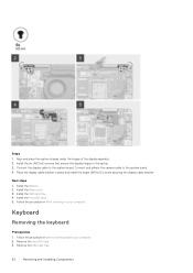
... the display cable bracket. Steps 1. Next steps 1. Keyboard Removing the keyboard Prerequisites 1. Install the six (M2.5x5) screws that secure the display hinges to the laptop. 3. Install the SIM card tray 4. Remove the microSD card. 3. Install the Battery. 2.
... the display cable bracket. Steps 1. Next steps 1. Keyboard Removing the keyboard Prerequisites 1. Install the six (M2.5x5) screws that secure the display hinges to the laptop. 3. Install the SIM card tray 4. Remove the microSD card. 3. Install the Battery. 2.


