
Owners Manual
Page 3
......11 Removing dummy SIM card tray ...11 Base cover...12 Removing base cover...12 Installing base cover...14 Battery...14 Lithium-ion battery precautions...14 Removing battery...14 Installing battery...15 PCIe Solid State Drive (SSD)...15 Removing PCIe SSD...15 Installing PCIe SSD...16 Speaker...17 Removing... speaker module...17 Installing speaker module...18 Coin cell battery...18 Removing the coin cell battery...18 Installing coin cell battery...19 WWAN card...19 Removing WWAN card...19 Installing WWAN card...20 WLAN card...20 Removing WLAN ...
......11 Removing dummy SIM card tray ...11 Base cover...12 Removing base cover...12 Installing base cover...14 Battery...14 Lithium-ion battery precautions...14 Removing battery...14 Installing battery...15 PCIe Solid State Drive (SSD)...15 Removing PCIe SSD...15 Installing PCIe SSD...16 Speaker...17 Removing... speaker module...17 Installing speaker module...18 Coin cell battery...18 Removing the coin cell battery...18 Installing coin cell battery...19 WWAN card...19 Removing WWAN card...19 Installing WWAN card...20 WLAN card...20 Removing WLAN ...

Owners Manual
Page 5
... 4 System specifications...60 Supported operating systems...60 Processor specifications...60 System specifications...61 Memory specifications...61 Storage specifications...61 Video specifications...61 Audio specifications...62 Battery specifications...62 AC adapter specifications...63 Docking options...63 Port and connector specifications...63 Communication specifications...64 Camera specifications...64 Touchpad specifications...64 Display specifications...
... 4 System specifications...60 Supported operating systems...60 Processor specifications...60 System specifications...61 Memory specifications...61 Storage specifications...61 Video specifications...61 Audio specifications...62 Battery specifications...62 AC adapter specifications...63 Docking options...63 Port and connector specifications...63 Communication specifications...64 Camera specifications...64 Touchpad specifications...64 Display specifications...

Owners Manual
Page 8
...the locking tabs before you disconnect a cable, pull on its connector or on its metal mounting bracket. Do not use only the battery designed for few seconds, to avoid bending any telephone or network cables to ground yourself before you disconnect the cable. CAUTION: To connect...is not covered by periodically touching an unpainted metal surface that shipped with care. CAUTION: To avoid damage to the computer, use batteries designed for other Dell computers. 1 Connect any external devices, such as a port replicator or media base, and replace any replacement procedure, ensure that...
...the locking tabs before you disconnect a cable, pull on its connector or on its metal mounting bracket. Do not use only the battery designed for few seconds, to avoid bending any telephone or network cables to ground yourself before you disconnect the cable. CAUTION: To connect...is not covered by periodically touching an unpainted metal surface that shipped with care. CAUTION: To avoid damage to the computer, use batteries designed for other Dell computers. 1 Connect any external devices, such as a port replicator or media base, and replace any replacement procedure, ensure that...

Owners Manual
Page 10
...• Phillips #1 screwdriver • Small plastic scribe Screw size list Table 1. Screw size list Component Back cover M2.5x 6.0 M2.5x5.0 8 (captive screw) Battery (3-cell) Battery (4-cell) SSD module Heat sink module System fan 2 WWAN card WLAN card Power connector port ESD bracket EDP bracket Touchpad buttons Fingerprint reader LED board... Display panel M2.0 x 5.0 M2.5 x 4.0 M2.0x3.0 1 2 1 4 2 1 1 1 1 2 1 1 2 6 • FHD - 2 • HD - 4 M2.0 x 2.5 2 M2.0 x 2.0 Keyboard support plate Keyboard System board 18 5 3 10 Disassembly and reassembly Latitude 7480 -
...• Phillips #1 screwdriver • Small plastic scribe Screw size list Table 1. Screw size list Component Back cover M2.5x 6.0 M2.5x5.0 8 (captive screw) Battery (3-cell) Battery (4-cell) SSD module Heat sink module System fan 2 WWAN card WLAN card Power connector port ESD bracket EDP bracket Touchpad buttons Fingerprint reader LED board... Display panel M2.0 x 5.0 M2.5 x 4.0 M2.0x3.0 1 2 1 4 2 1 1 1 1 2 1 1 2 6 • FHD - 2 • HD - 4 M2.0 x 2.5 2 M2.0 x 2.0 Keyboard support plate Keyboard System board 18 5 3 10 Disassembly and reassembly Latitude 7480 -

Owners Manual
Page 14
... much as possible before removing it from https://www.dell.com or authorized Dell partners and re-sellers. Contact https://www.dell.com/support for assistance and further instructions. • Always purchase genuine batteries from the system. c Lift the battery from the system to allow the battery to drain. • Do not crush, drop, mutilate, or...
... much as possible before removing it from https://www.dell.com or authorized Dell partners and re-sellers. Contact https://www.dell.com/support for assistance and further instructions. • Always purchase genuine batteries from the system. c Lift the battery from the system to allow the battery to drain. • Do not crush, drop, mutilate, or...

Owners Manual
Page 15
... un routed. 3 Tighten the M2.0 x 5.0 screws to secure the battery to the connector on the computer. 2 Route the battery cable through the routing clip and connect the battery cable to the computer. b Remove the SSD bracket [2]. NOTE: A small battery (3-cell) has a single screw, a larger battery (4-cell) has two screws. 4 Install the base cover 5 Follow the...
... un routed. 3 Tighten the M2.0 x 5.0 screws to secure the battery to the connector on the computer. 2 Route the battery cable through the routing clip and connect the battery cable to the computer. b Remove the SSD bracket [2]. NOTE: A small battery (3-cell) has a single screw, a larger battery (4-cell) has two screws. 4 Install the base cover 5 Follow the...

Owners Manual
Page 17
... speaker cable from the routing clips. Do not pull the cable as it may result in Before working inside your computer. 2 Remove the: a base cover b battery 3 To release the speaker module: a Push the pin to unroute the speaker cable from the computer . b Lift the speaker module from the routing clip. b Un...
... speaker cable from the routing clips. Do not pull the cable as it may result in Before working inside your computer. 2 Remove the: a base cover b battery 3 To release the speaker module: a Push the pin to unroute the speaker cable from the computer . b Lift the speaker module from the routing clip. b Un...

Owners Manual
Page 18
... release it from the connector on the system board. 4 Install the: a battery b base cover 5 Follow the procedure in Before working inside your computer. Coin cell battery Removing the coin cell battery 1 Follow the procedure in After working inside your computer. 2 Remove the :... a base cover b battery 3 To remove the coin cell battery: a Disconnect the coin cell battery cable from the adhesive [2]. 18 Disassembly...
... release it from the connector on the system board. 4 Install the: a battery b base cover 5 Follow the procedure in Before working inside your computer. Coin cell battery Removing the coin cell battery 1 Follow the procedure in After working inside your computer. 2 Remove the :... a base cover b battery 3 To remove the coin cell battery: a Disconnect the coin cell battery cable from the adhesive [2]. 18 Disassembly...

Owners Manual
Page 19
...2 Remove the : a base cover b battery 3 To remove the WWAN card: a Remove the M2.0 x 3.0 screw that secures the WWAN card . b Lift the metal bracket that secures the metal bracket to the connector on the system board. 4 Install the : a battery b base cover 5 Follow the procedure in... Before working inside your computer. Disassembly and reassembly 19 Installing coin cell battery 1 Affix the coin cell battery on the slot inside the computer. 2 Route the coin cell battery cable through the routing channel before ...
...2 Remove the : a base cover b battery 3 To remove the WWAN card: a Remove the M2.0 x 3.0 screw that secures the WWAN card . b Lift the metal bracket that secures the metal bracket to the connector on the system board. 4 Install the : a battery b base cover 5 Follow the procedure in... Before working inside your computer. Disassembly and reassembly 19 Installing coin cell battery 1 Affix the coin cell battery on the slot inside the computer. 2 Route the coin cell battery cable through the routing channel before ...

Owners Manual
Page 20
... cables to the connectors on the WWAN card. 3 Place the metal bracket and tighten the M2.0 x 3.0 screw to secure it to the computer. 4 Install the : a battery b base cover 5 Follow the procedure in Before working inside your computer. WLAN card Removing WLAN card 1 Follow the procedure in After working inside your computer...
... cables to the connectors on the WWAN card. 3 Place the metal bracket and tighten the M2.0 x 3.0 screw to secure it to the computer. 4 Install the : a battery b base cover 5 Follow the procedure in Before working inside your computer. WLAN card Removing WLAN card 1 Follow the procedure in After working inside your computer...

Owners Manual
Page 21
... WLAN card 1 Insert the WLAN card into the connector on the system board. 2 Connect the WLAN cables to the computer. 4 Install the .: a battery b base cover 5 Follow the procedure in After working inside your computer. NOTE: Ensure NOT to pull the WLAN card more than 35°, to avoid... damage to the WLAN card [1]. Disassembly and reassembly 21 b battery 3 To remove the WLAN card: a Remove the M2.0 x 3.0 screw that secures the metal bracket to pin. c Disconnect the WLAN cables from the computer ...
... WLAN card 1 Insert the WLAN card into the connector on the system board. 2 Connect the WLAN cables to the computer. 4 Install the .: a battery b base cover 5 Follow the procedure in After working inside your computer. NOTE: Ensure NOT to pull the WLAN card more than 35°, to avoid... damage to the WLAN card [1]. Disassembly and reassembly 21 b battery 3 To remove the WLAN card: a Remove the M2.0 x 3.0 screw that secures the metal bracket to pin. c Disconnect the WLAN cables from the computer ...

Owners Manual
Page 22
Installing memory module 1 Insert the memory module into the connector until snaps in. 2 Install the : a battery b base cover 3 Follow the procedures in Before working inside your computer. 22 Disassembly and reassembly b Remove the memory module from the connector on the system board [2]. Memory modules Removing memory module 1 Follow the procedure in After working inside your computer. 2 Remove the : a base cover b battery 3 To remove the memory module: a Pull the clips securing the memory module until the module snaps-out [1].
Installing memory module 1 Insert the memory module into the connector until snaps in. 2 Install the : a battery b base cover 3 Follow the procedures in Before working inside your computer. 22 Disassembly and reassembly b Remove the memory module from the connector on the system board [2]. Memory modules Removing memory module 1 Follow the procedure in After working inside your computer. 2 Remove the : a base cover b battery 3 To remove the memory module: a Pull the clips securing the memory module until the module snaps-out [1].

Owners Manual
Page 23
... assembly Heat sink assembly comprises of heat sink and the system fan. 1 Follow the procedure in Before working inside your computer. 2 Remove the: a base cover b battery 3 To remove the heat sink assembly: NOTE: To identify the number of the callout numbers [1, 2, 3, 4] as indicated on the system board . 2 Tighten the M2.0 x 3.0 screws...
... assembly Heat sink assembly comprises of heat sink and the system fan. 1 Follow the procedure in Before working inside your computer. 2 Remove the: a base cover b battery 3 To remove the heat sink assembly: NOTE: To identify the number of the callout numbers [1, 2, 3, 4] as indicated on the system board . 2 Tighten the M2.0 x 3.0 screws...
Owners Manual
Page 24
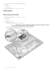
... release the LED cable. 3 Connect the fan cable to the connector on the system board. 4 Install the : a battery b base cover 5 Follow the procedure in After working inside your computer. 2 Remove the : a base cover b battery 3 To remove the LED board: a Disconnect the LED cable from the computer [3]. 24 Disassembly and reassembly LED board...
... release the LED cable. 3 Connect the fan cable to the connector on the system board. 4 Install the : a battery b base cover 5 Follow the procedure in After working inside your computer. 2 Remove the : a base cover b battery 3 To remove the LED board: a Disconnect the LED cable from the computer [3]. 24 Disassembly and reassembly LED board...

Owners Manual
Page 25
...the slot on the computer. 2 Tighten the M2.0 x 3.0screw to secure the LED board. 3 Connect the LED cable to the LED board. 4 Install the : a battery b base cover 5 Follow the procedure in Before working inside your computer. b Lift the smart card cable that is affixed to the smart card head. NOTE... with adhesive tape. Smart card module Removing smart card cage 1 Follow the procedure in After working inside your computer. 2 Remove the: a base cover b battery c PCIe SSD card 3 To disconnect the smart card cable: a Disconnect the smart card cable [1]. Disassembly and reassembly 25
...the slot on the computer. 2 Tighten the M2.0 x 3.0screw to secure the LED board. 3 Connect the LED cable to the LED board. 4 Install the : a battery b base cover 5 Follow the procedure in Before working inside your computer. b Lift the smart card cable that is affixed to the smart card head. NOTE... with adhesive tape. Smart card module Removing smart card cage 1 Follow the procedure in After working inside your computer. 2 Remove the: a base cover b battery c PCIe SSD card 3 To disconnect the smart card cable: a Disconnect the smart card cable [1]. Disassembly and reassembly 25
Owners Manual
Page 26
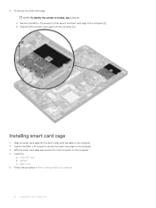
... [2]. Installing smart card cage 1 Slide the smart card cage into the slot to align with the tabs on the computer . 4 Install the: a PCIe SSD card b battery c base cover 5 Follow the procedure in After working inside your computer. 26 Disassembly and reassembly
... [2]. Installing smart card cage 1 Slide the smart card cage into the slot to align with the tabs on the computer . 4 Install the: a PCIe SSD card b battery c base cover 5 Follow the procedure in After working inside your computer. 26 Disassembly and reassembly

Owners Manual
Page 27
Touchpad buttons board Removing touchpad buttons board 1 Follow the procedure in Before working inside your computer. 2 Remove the: a base cover b battery c speaker 3 To disconnect the smart card cable: a Disconnect the smart card cable [1]. b Lift the smart card cable that secure the touchpad buttons board [2]. NOTE: To ...
Touchpad buttons board Removing touchpad buttons board 1 Follow the procedure in Before working inside your computer. 2 Remove the: a base cover b battery c speaker 3 To disconnect the smart card cable: a Disconnect the smart card cable [1]. b Lift the smart card cable that secure the touchpad buttons board [2]. NOTE: To ...

Owners Manual
Page 28
Power connector port Removing power connector port 1 Follow the procedure in After working inside your computer. 2 Remove the : a base cover b battery 3 To remove the power connector port: a Disconnect the power connector port cable from the system board [1]. 28 Disassembly and reassembly Installing touchpad buttons board 1 Insert ... cable to the connector on the touchpad board. 4 Affix the smart card cable and connect it to the connector on the computer 5 Install the: a speaker b battery c base cover 6 Follow the procedure in Before working inside your computer.
Power connector port Removing power connector port 1 Follow the procedure in After working inside your computer. 2 Remove the : a base cover b battery 3 To remove the power connector port: a Disconnect the power connector port cable from the system board [1]. 28 Disassembly and reassembly Installing touchpad buttons board 1 Insert ... cable to the connector on the touchpad board. 4 Affix the smart card cable and connect it to the connector on the computer 5 Install the: a speaker b battery c base cover 6 Follow the procedure in Before working inside your computer.
Owners Manual
Page 29
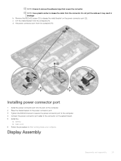
NOTE: Use a plastic scribe to the connector on the system board. 5 Install the : a battery b base cover 6 Follow the procedure in breakage b Remove the M2.0x3.0 screw (1) to remove the adhesive tape that covers the connector. Installing power connector port 1 ...
NOTE: Use a plastic scribe to the connector on the system board. 5 Install the : a battery b base cover 6 Follow the procedure in breakage b Remove the M2.0x3.0 screw (1) to remove the adhesive tape that covers the connector. Installing power connector port 1 ...

Owners Manual
Page 30
... to disconnect it on the system board [5]. Removing display assembly-with Touch 1 Follow the procedure in Before working inside your computer. 2 Remove the: a base cover b battery c WLAN card d WWAN card NOTE: To identify the number of screws, see screw list 3 To remove the display assembly: a Un route the WLAN and WWAN...
... to disconnect it on the system board [5]. Removing display assembly-with Touch 1 Follow the procedure in Before working inside your computer. 2 Remove the: a base cover b battery c WLAN card d WWAN card NOTE: To identify the number of screws, see screw list 3 To remove the display assembly: a Un route the WLAN and WWAN...


