Service Manual
Page 4
... instructions...7 Before working inside your computer...7 Safety precautions...8 Electrostatic discharge-ESD protection...8 ESD field service kit ...9 Transporting sensitive components...10 After working inside your computer...10 Chapter 2: Technology and components 11 USB features...11 USB Type-C...13 HDMI 1.4a...14 Power button LED behavior...15 Chapter 3: Major components of your system 17 Chapter 4: Disassembly and reassembly 19 MicroSD card...19 Removing the microSD card...19 Installing...
... instructions...7 Before working inside your computer...7 Safety precautions...8 Electrostatic discharge-ESD protection...8 ESD field service kit ...9 Transporting sensitive components...10 After working inside your computer...10 Chapter 2: Technology and components 11 USB features...11 USB Type-C...13 HDMI 1.4a...14 Power button LED behavior...15 Chapter 3: Major components of your system 17 Chapter 4: Disassembly and reassembly 19 MicroSD card...19 Removing the microSD card...19 Installing...
Service Manual
Page 7
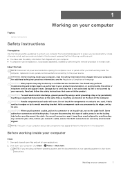
... using a different operating system, see the Regulatory Compliance Homepage CAUTION: Many repairs may appear differently than shown in reverse order. Do not touch the components or contacts on the cable itself. Click Start > Power > Shut down your computer. Unless otherwise noted, each procedure included in on the locking tabs before opening the computer cover or panels. You should only perform troubleshooting and simple repairs...
... using a different operating system, see the Regulatory Compliance Homepage CAUTION: Many repairs may appear differently than shown in reverse order. Do not touch the components or contacts on the cable itself. Click Start > Power > Shut down your computer. Unless otherwise noted, each procedure included in on the locking tabs before opening the computer cover or panels. You should only perform troubleshooting and simple repairs...
Service Manual
Page 8
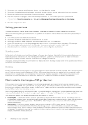
... the power button for 15 seconds should be remotely turned on (wake on an anti-static mat. ● Wear shoes with your computer Intermittent failures represent approximately 80 percent of device functionality. Disconnect all network cables, telephone, and telecommunications lines from their electrical outlets. 4. Standby power Dell products with standby power must be obvious, such as keyboard, mouse, and monitor from tablets.notebooks. Systems...
... the power button for 15 seconds should be remotely turned on (wake on an anti-static mat. ● Wear shoes with your computer Intermittent failures represent approximately 80 percent of device functionality. Disconnect all network cables, telephone, and telecommunications lines from their electrical outlets. 4. Standby power Dell products with standby power must be obvious, such as keyboard, mouse, and monitor from tablets.notebooks. Systems...
Service Manual
Page 10
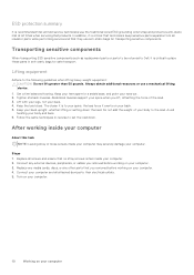
... electrical outlets. 5. Keep the load close. Replace any media cards, discs, or any external devices, peripherals, or cables you removed before working inside your computer About this task NOTE: Leaving stray or loose screws inside your toes out. 2. Tighten stomach muscles. Abdominal muscles support your spine when you removed before working on your computer. Connect any other parts that you lift, offsetting the force...
... electrical outlets. 5. Keep the load close. Replace any media cards, discs, or any external devices, peripherals, or cables you removed before working inside your computer About this task NOTE: Leaving stray or loose screws inside your toes out. 2. Tighten stomach muscles. Abdominal muscles support your spine when you removed before working on your computer. Connect any other parts that you lift, offsetting the force...

Service Manual
Page 11
... power-hungry devices ● New power management features ● Full-duplex data transfers and support for more speed grows by ever faster computing hardware and ever greater bandwidth demands. Speed Currently, there are Super-Speed, Hi-Speed and Full-Speed. USB 3.0/USB 3.1 Gen 1 achieves the much higher performance by the latest USB 3.0/USB 3.1 Gen 1 specification. They are 3 speed modes defined by the technical changes...
... power-hungry devices ● New power management features ● Full-duplex data transfers and support for more speed grows by ever faster computing hardware and ever greater bandwidth demands. Speed Currently, there are Super-Speed, Hi-Speed and Full-Speed. USB 3.0/USB 3.1 Gen 1 achieves the much higher performance by the latest USB 3.0/USB 3.1 Gen 1 specification. They are 3 speed modes defined by the technical changes...
Service Manual
Page 14
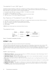
... 3D video formats, paving the way for a separate audio cable. ● 3D - USB Type-C connector and cables which are compact and reversible 3. Allows an HDMI-connected TV with a built-in digital photography and computer graphics. ● 4K Support - Thunderbolt 3 uses a USB Type-C connector/port to connect to 40 Gbps NOTE: Data transfer speed may vary between display and source devices, enabling a TV to 40 Gbps, creating one compact port that...
... 3D video formats, paving the way for a separate audio cable. ● 3D - USB Type-C connector and cables which are compact and reversible 3. Allows an HDMI-connected TV with a built-in digital photography and computer graphics. ● 4K Support - Thunderbolt 3 uses a USB Type-C connector/port to connect to 40 Gbps NOTE: Data transfer speed may vary between display and source devices, enabling a TV to 40 Gbps, creating one compact port that...
Service Manual
Page 15
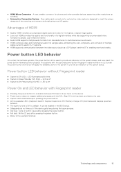
New cables and connectors for phones and other portable devices, supporting video resolutions up to 1080p. ● Automotive Connection System - Power button LED behavior On certain Dell Latitude systems, the power button LED is off ● System is Off/Hibernating (S4/S5) = LED is used in the system to the user. ● System LED's illuminates upon pressing the power button. ● All the available LED's (Keyboard backlit/ Keyboard caps lock LED/ Battery Charge LED) illuminates and displays specified behavior. ●...
New cables and connectors for phones and other portable devices, supporting video resolutions up to 1080p. ● Automotive Connection System - Power button LED behavior On certain Dell Latitude systems, the power button LED is off ● System is Off/Hibernating (S4/S5) = LED is used in the system to the user. ● System LED's illuminates upon pressing the power button. ● All the available LED's (Keyboard backlit/ Keyboard caps lock LED/ Battery Charge LED) illuminates and displays specified behavior. ●...
Service Manual
Page 87
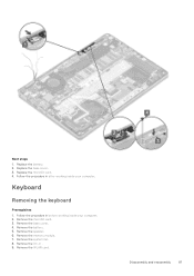
Remove the microSD card. 3. Remove the memory module. 7. Follow the procedure in after working inside your computer. 2. Remove the base cover. 4. Remove the system fan. 8. Replace the battery. 2. Replace the microSD card. 4. Remove the WLAN card. Remove the DC-in before working inside your computer. Disassembly and reassembly 87 Follow the procedure in . 9. Remove the battery. 5. Remove the speaker. 6. Keyboard Removing the keyboard Prerequisites 1. Replace the base cover. 3. Next steps 1.
Remove the microSD card. 3. Remove the memory module. 7. Follow the procedure in after working inside your computer. 2. Remove the base cover. 4. Remove the system fan. 8. Replace the battery. 2. Replace the microSD card. 4. Remove the WLAN card. Remove the DC-in before working inside your computer. Disassembly and reassembly 87 Follow the procedure in . 9. Remove the battery. 5. Remove the speaker. 6. Keyboard Removing the keyboard Prerequisites 1. Replace the base cover. 3. Next steps 1.
Service Manual
Page 121
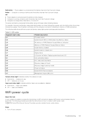
... ROM (Read-Only Memory) failure No memory or RAM (Random-Access Memory) detected Memory or RAM (Random-Access Memory) failure Invalid memory installed System-board or chipset error Display failure LCD power rail failure. The following table shows different power and battery-status light patterns and associated problems. Table 3. Camera is in use . Caps Lock enabled. ● Off - Steps 1. The power and battery-status light blinks amber along with beep codes indicating failures. Replace system board and LCD Coin-cell battery failure PCI, video card/chip failure Recovery...
... ROM (Read-Only Memory) failure No memory or RAM (Random-Access Memory) detected Memory or RAM (Random-Access Memory) failure Invalid memory installed System-board or chipset error Display failure LCD power rail failure. The following table shows different power and battery-status light patterns and associated problems. Table 3. Camera is in use . Caps Lock enabled. ● Off - Steps 1. The power and battery-status light blinks amber along with beep codes indicating failures. Replace system board and LCD Coin-cell battery failure PCI, video card/chip failure Recovery...
Setup and specifications guide
Page 7
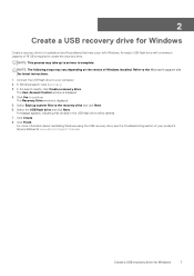
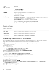
.... Click Create. 8. 2 Create a USB recovery drive for Windows Create a recovery drive to troubleshoot and fix problems that all data in the USB flash drive will be deleted. 7. Connect the USB flash drive to the recovery drive and click Next. 6. Click Finish. NOTE: This process may take up system files to your product's Service Manual at www.dell.com/support/manuals. In Windows search, type Recovery. 3. For more information about reinstalling Windows using the USB recovery drive, see the Troubleshooting section of 16 GB is displayed. 4. Select...
.... Click Create. 8. 2 Create a USB recovery drive for Windows Create a recovery drive to troubleshoot and fix problems that all data in the USB flash drive will be deleted. 7. Connect the USB flash drive to the recovery drive and click Next. 6. Click Finish. NOTE: This process may take up system files to your product's Service Manual at www.dell.com/support/manuals. In Windows search, type Recovery. 3. For more information about reinstalling Windows using the USB recovery drive, see the Troubleshooting section of 16 GB is displayed. 4. Select...
Setup and specifications guide
Page 25
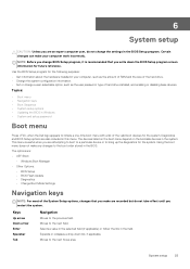
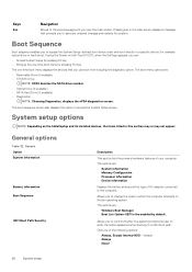
... Down arrow Enter Spacebar Tab Navigation Moves to the next field. The options are: • UEFI Boot: • Windows Boot Manager • Other Options: • BIOS Setup • BIOS Flash Update • Diagnostics • Change Boot Mode Settings Navigation keys NOTE: For most of the valid boot devices for the system. NOTE: Before you change a user-selectable option, such as the user password, type of hard drive installed, and enabling or disabling base devices. Diagnostics and BIOS Setup options are an expert computer user, do...
... Down arrow Enter Spacebar Tab Navigation Moves to the next field. The options are: • UEFI Boot: • Windows Boot Manager • Other Options: • BIOS Setup • BIOS Flash Update • Diagnostics • Change Boot Mode Settings Navigation keys NOTE: For most of the valid boot devices for the system. NOTE: Before you change a user-selectable option, such as the user password, type of hard drive installed, and enabling or disabling base devices. Diagnostics and BIOS Setup options are an expert computer user, do...
Setup and specifications guide
Page 26
... Setup-defined boot device order and boot directly to a specific device (for example: optical drive or hard drive). During the Power-on the tabletlaptop and its installed devices, the items listed in which the computer attempts to find an operating system. Click one -time boot menu displays the devices that prompts you to control whether the system prompts the user to enter the Admin password when booting to a UEFI boot path. Boot Sequence Boot sequence enables you to change...
... Setup-defined boot device order and boot directly to a specific device (for example: optical drive or hard drive). During the Power-on the tabletlaptop and its installed devices, the items listed in which the computer attempts to find an operating system. Click one -time boot menu displays the devices that prompts you to control whether the system prompts the user to enter the Admin password when booting to a UEFI boot path. Boot Sequence Boot sequence enables you to change...
Setup and specifications guide
Page 27
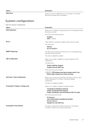
... device enumeration. NOTE: USB keyboard and mouse always work in the BIOS setup irrespective of the following security levels : • No Security • User Authentication (Enabled by Defualt) • Secure Connect • Display Port and USB Only This option configures the method used by default. This option is disabled by default. Click one of these settings. The options are: • Enable USB Boot Support • Enable External USB Ports All the options are reported during startup. Allows you enable or disable various drives on board. The change...
... device enumeration. NOTE: USB keyboard and mouse always work in the BIOS setup irrespective of the following security levels : • No Security • User Authentication (Enabled by Defualt) • Secure Connect • Display Port and USB Only This option configures the method used by default. This option is disabled by default. Click one of these settings. The options are: • Enable USB Boot Support • Enable External USB Ports All the options are reported during startup. Allows you enable or disable various drives on board. The change...
Setup and specifications guide
Page 29
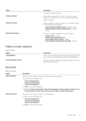
... change or delete the password. This option enables or disables the Dynamic Backlight Control if the panel supports the feature. NOTE: For the first time login, "Enter the old password:" field is default) and On AC (100% default). When enabled, pressing Fn+F7 will turn off all light and sound emission in the system. Disabled • Secure Digital Card (SD) Read-Only Mode - Enable or disable the Fingerprint Reader or the Fingerprint Reader Device...
... change or delete the password. This option enables or disables the Dynamic Backlight Control if the panel supports the feature. NOTE: For the first time login, "Enter the old password:" field is default) and On AC (100% default). When enabled, pressing Fn+F7 will turn off all light and sound emission in the system. Disabled • Secure Digital Card (SD) Read-Only Mode - Enable or disable the Fingerprint Reader or the Fingerprint Reader Device...
Setup and specifications guide
Page 30
... Enable, Disable, or Permanently Disable the BIOS module interface of the options: • Disabled-Default • Reboot bypass Allows you to update the system BIOS via hotkey during boot. Specifically this settings is capable of your password. The options are able to enter Option ROM Configuration screens via UEFI capsule update packages. • Enable UEFI Capsule Firmware Updates This option is set by default. You can change the System password when the administrator password is set. • Allow Non-Admin Password Changes This option is set by default. Options...
... Enable, Disable, or Permanently Disable the BIOS module interface of the options: • Disabled-Default • Reboot bypass Allows you to update the system BIOS via hotkey during boot. Specifically this settings is capable of your password. The options are able to enter Option ROM Configuration screens via UEFI capsule update packages. • Enable UEFI Capsule Firmware Updates This option is set by default. You can change the System password when the administrator password is set. • Allow Non-Admin Password Changes This option is set by default. Options...

Setup and specifications guide
Page 31
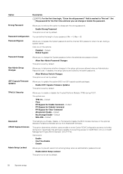
... Boot Feature. • Secure Boot Enable-Default Changes to the Secure Boot operation mode modifies the behaviour of Secure Boot to enable or disable Expert Key Management. • Enable Custom Mode This option is not set by default. NOTE: Hard Disk password should be cleared before the settings can be changed. Choose one of the following options: System setup 31 Intel Software Guard Extensions Option Intel SGX Enable Enclave Memory Size Description This field specifies you to disable master password support. • Enable Master Password...
... Boot Feature. • Secure Boot Enable-Default Changes to the Secure Boot operation mode modifies the behaviour of Secure Boot to enable or disable Expert Key Management. • Enable Custom Mode This option is not set by default. NOTE: Hard Disk password should be cleared before the settings can be changed. Choose one of the following options: System setup 31 Intel Software Guard Extensions Option Intel SGX Enable Enclave Memory Size Description This field specifies you to disable master password support. • Enable Master Password...
Setup and specifications guide
Page 33
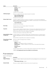
... from the wired network the selected wireless radio will sense the connection of time using Dell's fast charging technology. • Primarily AC use certain power adapters. • Enable Adapter Warnings-Default Allows you to block entering to enable or disable the Numlock function when the system boots. Advanced Battery Charge Mode can also configure Custom Charge Start and Custom Charge Stop. Upon disconnection from standby. • Enable USB Wake Support • Wake on Dell USB-C Dock This option is selected...
... from the wired network the selected wireless radio will sense the connection of time using Dell's fast charging technology. • Primarily AC use certain power adapters. • Enable Adapter Warnings-Default Allows you to block entering to enable or disable the Numlock function when the system boots. Advanced Battery Charge Mode can also configure Custom Charge Start and Custom Charge Stop. Upon disconnection from standby. • Enable USB Wake Support • Wake on Dell USB-C Dock This option is selected...
Setup and specifications guide
Page 34
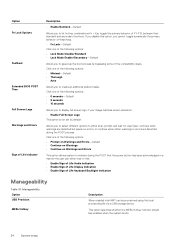
... Life Audio Indication • Enable Sign of Life Display Indication • Enable Sign of Life Keyboard Backlight Indication Manageability Table 41. Option Fn Lock Options Fastboot Extended BIOS POST Time Full Screen Logo Warnings and Errors Sign of Life Indicator Description • Enable Numlock-Default Allows you to select different options to either stop, prompt and wait for user input, continue when warnings are detected during the POST that the power button...
... Life Audio Indication • Enable Sign of Life Display Indication • Enable Sign of Life Keyboard Backlight Indication Manageability Table 41. Option Fn Lock Options Fastboot Extended BIOS POST Time Full Screen Logo Warnings and Errors Sign of Life Indicator Description • Enable Numlock-Default Allows you to select different options to either stop, prompt and wait for user input, continue when warnings are detected during the POST that the power button...
Setup and specifications guide
Page 36
... Next Boot This option is available. Allows you to Dell.com/support. • Enter the Service Tag or Express Service Code and click Submit. • Click Detect Product and follow the instructions on the HDD or an external USB drive. For laptops, ensure that your BIOS (System Setup), when you replace the system board or if an update is not set by default. Go to recover the corrupted BIOS from Hard Drive-This option is set by default...
... Next Boot This option is available. Allows you to Dell.com/support. • Enter the Service Tag or Express Service Code and click Submit. • Click Detect Product and follow the instructions on the HDD or an external USB drive. For laptops, ensure that your BIOS (System Setup), when you replace the system board or if an update is not set by default. Go to recover the corrupted BIOS from Hard Drive-This option is set by default...
Setup and specifications guide
Page 37
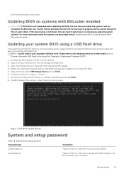
... must enter to access and make changes to display the One Time Boot Menu. 5. System setup 37 Updating BIOS on Dell Systems With BitLocker Enabled Updating your computer. The system will then be prompted to enter the recovery key to your system. Figure 1. If the recovery key is still a need to use a bootable USB flash drive. Download the BIOS update .EXE file to a Diag C:\> prompt. 7. System and setup password Password type System password Setup password Description Password that you must enter to log on each reboot...
... must enter to access and make changes to display the One Time Boot Menu. 5. System setup 37 Updating BIOS on Dell Systems With BitLocker Enabled Updating your computer. The system will then be prompted to enter the recovery key to your system. Figure 1. If the recovery key is still a need to use a bootable USB flash drive. Download the BIOS update .EXE file to a Diag C:\> prompt. 7. System and setup password Password type System password Setup password Description Password that you must enter to log on each reboot...


