
Owner's Manual
Page 3
...) Card...9 Installing The Secure Digital (SD) Card...9 Removing The Battery...9 Installing The Battery...10 Removing The Base Cover...10 Installing The Base Cover...10 Removing The Memory...10 Installing The Memory...11 Removing The Hard Drive...11 Installing The Hard Drive...12 Removing The Display Bezel...12 Installing the Display Bezel...13 Removing The Camera...13 Installing The Camera...13...
...) Card...9 Installing The Secure Digital (SD) Card...9 Removing The Battery...9 Installing The Battery...10 Removing The Base Cover...10 Installing The Base Cover...10 Removing The Memory...10 Installing The Memory...11 Removing The Hard Drive...11 Installing The Hard Drive...12 Removing The Display Bezel...12 Installing the Display Bezel...13 Removing The Camera...13 Installing The Camera...13...
Owner's Manual
Page 11
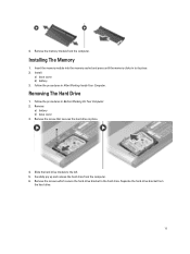
...: a) base cover b) battery 3. Removing The Hard Drive 1. Slide the hard drive module to its place. 2. Remove the screws which secure the hard-drive bracket to the hard drive. Separate the hard-drive bracket from the computer. 4. Follow the procedures in Before Working On Your Computer. 2. Remove the memory module from the hard drive. 11 Remove: a) battery b) base cover 3. Remove the screw that secures the hard drive in to the...
...: a) base cover b) battery 3. Removing The Hard Drive 1. Slide the hard drive module to its place. 2. Remove the screws which secure the hard-drive bracket to the hard drive. Separate the hard-drive bracket from the computer. 4. Follow the procedures in Before Working On Your Computer. 2. Remove the memory module from the hard drive. 11 Remove: a) battery b) base cover 3. Remove the screw that secures the hard drive in to the...
Owner's Manual
Page 12
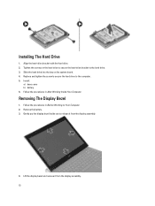
.... 4. Follow the procedures in After Working Inside Your Computer. Lift the display bezel and remove it from the display assembly. 12 Slide the hard drive into the bay on the hard drive to secure the hard-drive bracket to the computer. 5. Removing The Display Bezel 1. Remove the battery. 3. Install: a) base cover b) battery 6. Follow the procedures in Before Working on...
.... 4. Follow the procedures in After Working Inside Your Computer. Lift the display bezel and remove it from the display assembly. 12 Slide the hard drive into the bay on the hard drive to secure the hard-drive bracket to the computer. 5. Removing The Display Bezel 1. Remove the battery. 3. Install: a) base cover b) battery 6. Follow the procedures in Before Working on...

Owner's Manual
Page 16
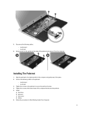
Follow the procedures in the computer. 4. Remove the screws from the bottom of the computer, that secures the palmrest. 4. Installing The Keyboard 1. Install the battery. 5. Removing The Palmrest 1. Press down until the keyboard clicks into place in After Working Inside Your Computer. Remove the screws on the palmrest. 16 Follow the procedures in its compartment. 3. Connect the keyboard cable to the system board. 2. Remove: a) battery b) base cover c) keyboard d) hard drive 3. Insert the keyboard in Before Working On Your Computer. 2.
Follow the procedures in the computer. 4. Remove the screws from the bottom of the computer, that secures the palmrest. 4. Installing The Keyboard 1. Install the battery. 5. Removing The Palmrest 1. Press down until the keyboard clicks into place in After Working Inside Your Computer. Remove the screws on the palmrest. 16 Follow the procedures in its compartment. 3. Connect the keyboard cable to the system board. 2. Remove: a) battery b) base cover c) keyboard d) hard drive 3. Insert the keyboard in Before Working On Your Computer. 2.
Owner's Manual
Page 17
media board - Install: a) hard drive b) keyboard c) base cover d) battery 6. touch pad 6. media board - Connect the following cables: - 5. Disconnect the following cables to the palmrest: - Align the palmrest to secure the ... Using a plastic scribe, gently pry the sides of the computer that secures the palmrest. 5. Tighten the screws at the bottom base of the palmrest and remove it into place. 2.
media board - Install: a) hard drive b) keyboard c) base cover d) battery 6. touch pad 6. media board - Connect the following cables: - 5. Disconnect the following cables to the palmrest: - Align the palmrest to secure the ... Using a plastic scribe, gently pry the sides of the computer that secures the palmrest. 5. Tighten the screws at the bottom base of the palmrest and remove it into place. 2.

Owner's Manual
Page 18
... Working Inside Your Computer. Connect the antenna cables to the computer. 3. Remove: a) battery b) base cover c) hard drive d) keyboard e) palmrest 3. Insert the WLAN card into its connector. 2. Remove: a) battery b) base cover c) hard drive d) keyboard e) palmrest 3. Removing The Display Assembly 1. Remove the screw that secures the display assembly. 18 Press the WLAN card down...cables from the computer base that secures the WLAN card. 5. Installing The Wireless Local Area Network (WLAN) Card 1. Install: a) palmrest b) keyboard c) hard drive d) base cover e) battery 5.
... Working Inside Your Computer. Connect the antenna cables to the computer. 3. Remove: a) battery b) base cover c) hard drive d) keyboard e) palmrest 3. Insert the WLAN card into its connector. 2. Remove: a) battery b) base cover c) hard drive d) keyboard e) palmrest 3. Removing The Display Assembly 1. Remove the screw that secures the display assembly. 18 Press the WLAN card down...cables from the computer base that secures the WLAN card. 5. Installing The Wireless Local Area Network (WLAN) Card 1. Install: a) palmrest b) keyboard c) hard drive d) base cover e) battery 5.
Owner's Manual
Page 21
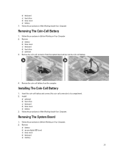
... 1. Follow the procedures in After Working Inside Your Computer. Remove the coin-cell connector from the computer. Installing The Coin-Cell Battery 1. Remove: a) battery b) secure digital (SD) card c) base cover d) keyboard e) memory 21 Follow the procedures in Before Working on Your Computer. 2. Install: a) palmrest b) hard drive c) keyboard d) base cover e) battery 3. Follow the procedures in...
... 1. Follow the procedures in After Working Inside Your Computer. Remove the coin-cell connector from the computer. Installing The Coin-Cell Battery 1. Remove: a) battery b) secure digital (SD) card c) base cover d) keyboard e) memory 21 Follow the procedures in Before Working on Your Computer. 2. Install: a) palmrest b) hard drive c) keyboard d) base cover e) battery 3. Follow the procedures in...
Owner's Manual
Page 22
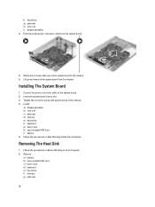
... system board from the system board. 4. Installing The System Board 1. Tighten the screws to secure the system board to the system board. 2. f) hard drive g) palmrest h) coin-cell i) display assembly 3. Remove the screws that secure the system board to the chassis. 5. Disconnect the power connector cable from the chassis. Insert the system board into...
... system board from the system board. 4. Installing The System Board 1. Tighten the screws to secure the system board to the system board. 2. f) hard drive g) palmrest h) coin-cell i) display assembly 3. Remove the screws that secure the system board to the chassis. 5. Disconnect the power connector cable from the chassis. Insert the system board into...
Owner's Manual
Page 23
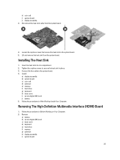
Installing The Heat Sink 1. Remove: a) battery b) secure digital (SD) card c) base cover d) keyboard e) hard drive f) memory g) palmrest h) display assembly i) system board 23 Loosen the captive screws that secure the heat sink... Insert the heat sink into its compartment. 2. Follow the procedures in Before Working on Your Computer. 2. Removing The High-Definition Multimedia Interface (HDMI) Board 1. Install: a) display assembly b) system board c) coin-cell d) palmrest e) memory f) hard drive g) keyboard h) base cover i) secure digital (SD) card j) battery 5. h) coin-cell i) system...
Installing The Heat Sink 1. Remove: a) battery b) secure digital (SD) card c) base cover d) keyboard e) hard drive f) memory g) palmrest h) display assembly i) system board 23 Loosen the captive screws that secure the heat sink... Insert the heat sink into its compartment. 2. Follow the procedures in Before Working on Your Computer. 2. Removing The High-Definition Multimedia Interface (HDMI) Board 1. Install: a) display assembly b) system board c) coin-cell d) palmrest e) memory f) hard drive g) keyboard h) base cover i) secure digital (SD) card j) battery 5. h) coin-cell i) system...
Owner's Manual
Page 24
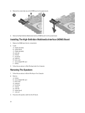
... compartment. 2. Installing The High-Definition Multimedia Interface (HDMI) Board 1. Follow the procedures in Before Working on Your Computer. 2. Remove: a) battery b) secure digital (SD) card c) base cover d) keyboard e) hard drive f) memory g) palmrest h) system board i) coin-cell 3. Remove the High-Definition Multimedia Interface (HDMI) board from the I/O board. 24 Disconnect the speaker cable from the system...
... compartment. 2. Installing The High-Definition Multimedia Interface (HDMI) Board 1. Follow the procedures in Before Working on Your Computer. 2. Remove: a) battery b) secure digital (SD) card c) base cover d) keyboard e) hard drive f) memory g) palmrest h) system board i) coin-cell 3. Remove the High-Definition Multimedia Interface (HDMI) board from the I/O board. 24 Disconnect the speaker cable from the system...
Owner's Manual
Page 25
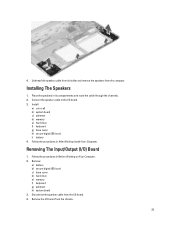
... Input/Output (I /O board. 3. Follow the procedures in its holder and remove the speakers from the computer. Disconnect the speaker cable from the chassis. 25 Remove: a) battery b) secure digital (SD) card c) base cover d) hard drive e) memory f) keyboard g) palmrest h) system board 3. Remove the I/O board from the I/O board. 4. 4. Place the speakers in Before Working on Your Computer. 2. Follow...
... Input/Output (I /O board. 3. Follow the procedures in its holder and remove the speakers from the computer. Disconnect the speaker cable from the chassis. 25 Remove: a) battery b) secure digital (SD) card c) base cover d) hard drive e) memory f) keyboard g) palmrest h) system board 3. Remove the I/O board from the I/O board. 4. 4. Place the speakers in Before Working on Your Computer. 2. Follow...
Owner's Manual
Page 26
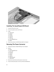
... Your Computer. 2. Follow the procedures in After Working Inside Your Computer. Remove the screw that secures the power connector port. 4. Lift up and remove the power connector port from the bottom base. 26 Installing The Input/Output (I/O) Board 1. Remove: a) battery b) secure digital (SD) card c) base cover d) hard drive e) palmrest f) memory g) keyboard h) display assembly i) system board...
... Your Computer. 2. Follow the procedures in After Working Inside Your Computer. Remove the screw that secures the power connector port. 4. Lift up and remove the power connector port from the bottom base. 26 Installing The Input/Output (I/O) Board 1. Remove: a) battery b) secure digital (SD) card c) base cover d) hard drive e) palmrest f) memory g) keyboard h) display assembly i) system board...

Owner's Manual
Page 35
... Dell logo appears, you can: • Access System Setup by pressing key • Bring up the one-time boot menu by pressing key The one-time boot menu displays the devices that you make are : • Removable Drive (if available) • STXXXX Drive NOTE: XXX denotes the SATA drive ...8208;defined boot device order and boot directly to a specific device (for example: optical drive or hard drive). The boot-menu options are recorded but do not take effect until you add or remove hardware • View the system hardware configuration • Enable or disable integrated devices &#...
... Dell logo appears, you can: • Access System Setup by pressing key • Bring up the one-time boot menu by pressing key The one-time boot menu displays the devices that you make are : • Removable Drive (if available) • STXXXX Drive NOTE: XXX denotes the SATA drive ...8208;defined boot device order and boot directly to a specific device (for example: optical drive or hard drive). The boot-menu options are recorded but do not take effect until you add or remove hardware • View the system hardware configuration • Enable or disable integrated devices &#...
Statement of Volatility
Page 2
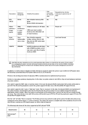
...All other components on the system board lose data if power is the "soft" off Hard drive(s) User Non Volatile magnetic Yes replaceable, media, various sizes in any context to prevent ...table shows all user data on the system configuration and time-ofday information. S5 is removed from the non-volatile storage can occur. cache or memory. The following is provided... write the system context to RAM" state or stand-by Dell Latitude™ 3330: Model Number S0 S1 S3 S4 S5 Dell Latitude™ X X X X X 3330 frame buffer UMA architectur e- In this state, the dynamic RAM...
...All other components on the system board lose data if power is the "soft" off Hard drive(s) User Non Volatile magnetic Yes replaceable, media, various sizes in any context to prevent ...table shows all user data on the system configuration and time-ofday information. S5 is removed from the non-volatile storage can occur. cache or memory. The following is provided... write the system context to RAM" state or stand-by Dell Latitude™ 3330: Model Number S0 S1 S3 S4 S5 Dell Latitude™ X X X X X 3330 frame buffer UMA architectur e- In this state, the dynamic RAM...


