E-Family Re-Image Guide
Page 10
Dell Latitude Ultrabook, E-Family & Mobile Precision Reimage "How-To" Guide 2.4.2 Installation Sequence & Features at a Glance: 2.4.2.1 BIOS, Drivers and Firmware: o BIOS o Intel Chipset - o Dell Desktop System Software - Enhances and optimizes video performance 2. Even if you do...1. Installs and enables the security devices & controllers 2. Wireless Local Area Network Adapters (WLAN) - Enables and enhances the Media Memory / SmartCard controller o Intel Storage: 1. Intelligent power sharing across cores 3. Enhances System Manageability Helps Windows control system board components ...
Dell Latitude Ultrabook, E-Family & Mobile Precision Reimage "How-To" Guide 2.4.2 Installation Sequence & Features at a Glance: 2.4.2.1 BIOS, Drivers and Firmware: o BIOS o Intel Chipset - o Dell Desktop System Software - Enhances and optimizes video performance 2. Even if you do...1. Installs and enables the security devices & controllers 2. Wireless Local Area Network Adapters (WLAN) - Enables and enhances the Media Memory / SmartCard controller o Intel Storage: 1. Intelligent power sharing across cores 3. Enhances System Manageability Helps Windows control system board components ...
E-Family Re-Image Guide
Page 14
... of Integrated Wired Network Controller. (see more detail in chapter 2.6.22) 2.6.3 Media Memory Card Controller o Microsoft Operating Systems do not include the Memory Card controller driver. Dell Latitude Ultrabook, E-Family & Mobile Precision Reimage "How-To" Guide 2.6 Recommended Drivers / Applications Installation Order For best results, Dell recommends installing drivers / applications in the following driver provided by...
... of Integrated Wired Network Controller. (see more detail in chapter 2.6.22) 2.6.3 Media Memory Card Controller o Microsoft Operating Systems do not include the Memory Card controller driver. Dell Latitude Ultrabook, E-Family & Mobile Precision Reimage "How-To" Guide 2.6 Recommended Drivers / Applications Installation Order For best results, Dell recommends installing drivers / applications in the following driver provided by...

Owner's Manual
Page 3
... Secure Digital (SD) Card...9 Removing The Battery...9 Installing The Battery...10 Removing The Base Cover...10 Installing The Base Cover...10 Removing The Memory...10 Installing The Memory...11 Removing The Hard Drive...11 Installing The Hard Drive...12 Removing The Display Bezel...12 Installing the Display Bezel...13 Removing The Camera...
... Secure Digital (SD) Card...9 Removing The Battery...9 Installing The Battery...10 Removing The Base Cover...10 Installing The Base Cover...10 Removing The Memory...10 Installing The Memory...11 Removing The Hard Drive...11 Installing The Hard Drive...12 Removing The Display Bezel...12 Installing the Display Bezel...13 Removing The Camera...

Owner's Manual
Page 7
...any telephone or network cables to the computer, use batteries designed for this particular Dell computer. CAUTION: To avoid damage to your computer. Do not use only the battery designed for other Dell computers. 1. Connect your computer and all attached devices to their electrical outlets.... 5. Inside View - hard drive 2. memory 3. Replace the battery. 4. battery bay 4. Turn on your computer. After...
...any telephone or network cables to the computer, use batteries designed for this particular Dell computer. CAUTION: To avoid damage to your computer. Do not use only the battery designed for other Dell computers. 1. Connect your computer and all attached devices to their electrical outlets.... 5. Inside View - hard drive 2. memory 3. Replace the battery. 4. battery bay 4. Turn on your computer. After...

Owner's Manual
Page 10
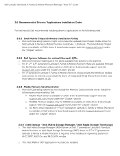
... procedures in After Working Inside Your Computer. Follow the procedures in Before Working On Your Computer. 2. Pry the retention clips away from the memory module till the memory module pops up and away from the computer. Slide the base cover towards the back of the base cover on the computer and slide... up . 10 Lift it on the computer. 2. Remove: a) Battery b) Base Cover 3. Insert the battery into its slot until the battery clicks into place. 2. Removing The Memory 1. Installing The Battery 1.
... procedures in After Working Inside Your Computer. Follow the procedures in Before Working On Your Computer. 2. Pry the retention clips away from the memory module till the memory module pops up and away from the computer. Slide the base cover towards the back of the base cover on the computer and slide... up . 10 Lift it on the computer. 2. Remove: a) Battery b) Base Cover 3. Insert the battery into its slot until the battery clicks into place. 2. Removing The Memory 1. Installing The Battery 1.
Owner's Manual
Page 11
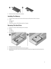
... in place. 4. Install: a) base cover b) battery 3. Remove: a) battery b) base cover 3. Removing The Hard Drive 1. Installing The Memory 1. Follow the procedures in Before Working On Your Computer. 2. Slide the hard drive module to its place. 2. Separate the hard-drive bracket from the computer. 6. ... and remove the hard drive from the hard drive. 11 Remove the screws which secure the hard-drive bracket to the hard drive. Remove the memory module from the computer.
... in place. 4. Install: a) base cover b) battery 3. Remove: a) battery b) base cover 3. Removing The Hard Drive 1. Installing The Memory 1. Follow the procedures in Before Working On Your Computer. 2. Slide the hard drive module to its place. 2. Separate the hard-drive bracket from the computer. 6. ... and remove the hard drive from the hard drive. 11 Remove the screws which secure the hard-drive bracket to the hard drive. Remove the memory module from the computer.
Owner's Manual
Page 21
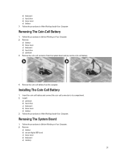
... drive e) palmrest 3. Insert the coin-cell battery and connect the coin-cell connector to its compartment. 2. Remove: a) battery b) secure digital (SD) card c) base cover d) keyboard e) memory 21 b) keyboard c) hard drive d) base cover e) battery 7. Install: a) palmrest b) hard drive c) keyboard d) base cover e) battery 3. Follow the procedures in Before Working on Your Computer. 2. Follow...
... drive e) palmrest 3. Insert the coin-cell battery and connect the coin-cell connector to its compartment. 2. Remove: a) battery b) secure digital (SD) card c) base cover d) keyboard e) memory 21 b) keyboard c) hard drive d) base cover e) battery 7. Install: a) palmrest b) hard drive c) keyboard d) base cover e) battery 3. Follow the procedures in Before Working on Your Computer. 2. Follow...
Owner's Manual
Page 22
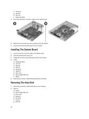
... system board to the system board. 2. Follow the procedures in After Working Inside Your Computer. Installing The System Board 1. Install: a) display assembly b) coin-cell c) palmrest d) memory e) hard drive f) keyboard g) base cover h) secure digital (SD) Card i) battery 5. Remove the screws that secure the system board to the chassis. 5. Removing The Heat Sink.... Insert the system board into its slot. 3. f) hard drive g) palmrest h) coin-cell i) display assembly 3. Remove: a) battery b) secure digital (SD) card c) base cover d) keyboard e) hard drive f) memory g) palmrest 22
... system board to the system board. 2. Follow the procedures in After Working Inside Your Computer. Installing The System Board 1. Install: a) display assembly b) coin-cell c) palmrest d) memory e) hard drive f) keyboard g) base cover h) secure digital (SD) Card i) battery 5. Remove the screws that secure the system board to the chassis. 5. Removing The Heat Sink.... Insert the system board into its slot. 3. f) hard drive g) palmrest h) coin-cell i) display assembly 3. Remove: a) battery b) secure digital (SD) card c) base cover d) keyboard e) hard drive f) memory g) palmrest 22
Owner's Manual
Page 23
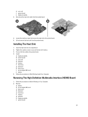
... the procedures in After Working Inside Your Computer. Remove: a) battery b) secure digital (SD) card c) base cover d) keyboard e) hard drive f) memory g) palmrest h) display assembly i) system board 23 Tighten the captive screws to secure the heat sink in place. 3. Install: a) display assembly b) ...system board c) coin-cell d) palmrest e) memory f) hard drive g) keyboard h) base cover i) secure digital (SD) card j) battery 5. Insert the heat sink into its compartment. 2. Disconnect...
... the procedures in After Working Inside Your Computer. Remove: a) battery b) secure digital (SD) card c) base cover d) keyboard e) hard drive f) memory g) palmrest h) display assembly i) system board 23 Tighten the captive screws to secure the heat sink in place. 3. Install: a) display assembly b) ...system board c) coin-cell d) palmrest e) memory f) hard drive g) keyboard h) base cover i) secure digital (SD) card j) battery 5. Insert the heat sink into its compartment. 2. Disconnect...
Owner's Manual
Page 24
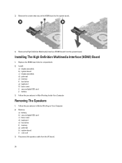
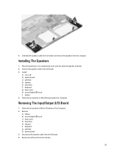
...High-Definition Multimedia Interface (HDMI) board from the I/O board. 24 Install: a) display assembly b) system board c) display assembly d) palmrest e) memory f) hard drive g) keyboard h) base cover i) secure digital (SD) card j) battery 3. Remove: a) battery b) secure digital (SD) card c) base cover... d) keyboard e) hard drive f) memory g) palmrest h) system board i) coin-cell 3. Replace the HDMI board into its compartment. 2. Removing The Speakers 1. Follow the procedures in After...
...High-Definition Multimedia Interface (HDMI) board from the I/O board. 24 Install: a) display assembly b) system board c) display assembly d) palmrest e) memory f) hard drive g) keyboard h) base cover i) secure digital (SD) card j) battery 3. Remove: a) battery b) secure digital (SD) card c) base cover... d) keyboard e) hard drive f) memory g) palmrest h) system board i) coin-cell 3. Replace the HDMI board into its compartment. 2. Removing The Speakers 1. Follow the procedures in After...
Owner's Manual
Page 25
... cover h) secure digital (SD) card i) battery 4. Follow the procedures in After Working Inside Your Computer. Remove: a) battery b) secure digital (SD) card c) base cover d) hard drive e) memory f) keyboard g) palmrest h) system board 3. 4. Place the speakers in its holder and remove the speakers from its compartments and route the cable through the channels. 2. Unthread...
... cover h) secure digital (SD) card i) battery 4. Follow the procedures in After Working Inside Your Computer. Remove: a) battery b) secure digital (SD) card c) base cover d) hard drive e) memory f) keyboard g) palmrest h) system board 3. 4. Place the speakers in its holder and remove the speakers from its compartments and route the cable through the channels. 2. Unthread...
Owner's Manual
Page 26
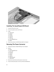
...After Working Inside Your Computer. Remove: a) battery b) secure digital (SD) card c) base cover d) hard drive e) palmrest f) memory g) keyboard h) display assembly i) system board 3. Lift up and remove the power connector port from the bottom base. 26 Follow ...the procedures in Before Working on Your Computer. 2. Removing The Power Connector 1. Install: a) system board b) palmrest c) memory d) hard drive e) keyboard f) base cover g) secure digital (SD) card h) battery 4. Installing The Input/Output (I /O board into its slot. 2. Insert ...
...After Working Inside Your Computer. Remove: a) battery b) secure digital (SD) card c) base cover d) hard drive e) palmrest f) memory g) keyboard h) display assembly i) system board 3. Lift up and remove the power connector port from the bottom base. 26 Follow ...the procedures in Before Working on Your Computer. 2. Removing The Power Connector 1. Install: a) system board b) palmrest c) memory d) hard drive e) keyboard f) base cover g) secure digital (SD) card h) battery 4. Installing The Input/Output (I /O board into its slot. 2. Insert ...
Owner's Manual
Page 27
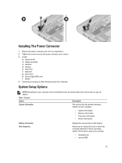
... of the battery. Allows you to find an operating system. Install: a) system board b) display assembly c) palmrest d) memory e) hard drive f) keyboard g) base cover h) decure digital (SD) card i) battery 4. System Setup Options NOTE: Depending on your computer.... • System Information • Memory Information • Processor Information • Device Information Battery Information Boot Sequence Displays the charge status of your computer and its compartment...
... of the battery. Allows you to find an operating system. Install: a) system board b) display assembly c) palmrest d) memory e) hard drive f) keyboard g) base cover h) decure digital (SD) card i) battery 4. System Setup Options NOTE: Depending on your computer.... • System Information • Memory Information • Processor Information • Device Information Battery Information Boot Sequence Displays the charge status of your computer and its compartment...

Owner's Manual
Page 36
... the Boot List option. Expands or collapses a drop‐down list, if applicable. System Setup Options NOTE: Depending on your computer. • System Information • Memory Information • Processor Information • Device Information Battery Information Boot Sequence Displays the charge status of your computer and its installed devices, the items listed...
... the Boot List option. Expands or collapses a drop‐down list, if applicable. System Setup Options NOTE: Depending on your computer. • System Information • Memory Information • Processor Information • Device Information Battery Information Boot Sequence Displays the charge status of your computer and its installed devices, the items listed...

Owner's Manual
Page 47
... Intel Celeron processors • Intel HD 3000 Graphics for 2nd Generation Intel processors • Intel HD 4000 Graphics for 3rd Generation Intel processors Memory Memory connector Memory capacity Memory type Minimum memory Maximum memory Two SODIMM slots 2 GB, 4 GB, and 8 GB • 1333MHz DDR3 for 2nd Generation Intel processors • 1600MHz DDR3L for 3rd Generation Intel...
... Intel Celeron processors • Intel HD 3000 Graphics for 2nd Generation Intel processors • Intel HD 4000 Graphics for 3rd Generation Intel processors Memory Memory connector Memory capacity Memory type Minimum memory Maximum memory Two SODIMM slots 2 GB, 4 GB, and 8 GB • 1333MHz DDR3 for 2nd Generation Intel processors • 1600MHz DDR3L for 3rd Generation Intel...

Owner's Manual
Page 48
... Type Controller Stereo Conversion Interface: Internal External Speakers Internal speaker amplifier Volume controls Communications Network adapter Wireless Ports and Connectors Audio Video Network adapter USB Memory card reader Display Type Size Active area (X/Y) Dimensions: Height Width Z-height Diagonal Maximum resolution Maximum Brightness 48 Two-channel high definition audio IDT 92HD93 24...
... Type Controller Stereo Conversion Interface: Internal External Speakers Internal speaker amplifier Volume controls Communications Network adapter Wireless Ports and Connectors Audio Video Network adapter USB Memory card reader Display Type Size Active area (X/Y) Dimensions: Height Width Z-height Diagonal Maximum resolution Maximum Brightness 48 Two-channel high definition audio IDT 92HD93 24...
Setup And Features Information
Page 2
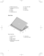
speaker 14. battery 3. memory card reader 2 device status lights 13. USB 2.0 connector with USB PowerShare 6. speaker 10. security lock slot 2. HDMI connector 5. Back View 1. touchpad buttons (2) Back View 12. power connector 4. cooling vents 7. touchpad 11. keyboard 15. power button Figure 2. headphone and microphone connector 9. USB 3.0 connectors (2) 8. 7.
speaker 14. battery 3. memory card reader 2 device status lights 13. USB 2.0 connector with USB PowerShare 6. speaker 10. security lock slot 2. HDMI connector 5. Back View 1. touchpad buttons (2) Back View 12. power connector 4. cooling vents 7. touchpad 11. keyboard 15. power button Figure 2. headphone and microphone connector 9. USB 3.0 connectors (2) 8. 7.
Statement of Volatility
Page 1
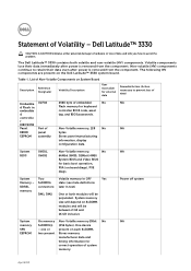
...DDR3L connectors: later in text) memory DM1, DM2 One or both volatile and non-volatile (NV) components. one or present on the Dell Latitude™ 3330 system board. Statement of data and tells you how to avoid the problem. Dell Latitude™ 3330 CAUTION: A CAUTION indicates either ... immediately after power is removed from the component. The Dell Latitude™ 3330 contains both modules will be between 2 GB and 16 GB inclusive Power off system System On memory Non-Volatile memory 2Kbit No NA memory SoDIMM(s) (256 bytes). Volatile components lose their data ...
...DDR3L connectors: later in text) memory DM1, DM2 One or both volatile and non-volatile (NV) components. one or present on the Dell Latitude™ 3330 system board. Statement of data and tells you how to avoid the problem. Dell Latitude™ 3330 CAUTION: A CAUTION indicates either ... immediately after power is removed from the component. The Dell Latitude™ 3330 contains both modules will be between 2 GB and 16 GB inclusive Power off system System On memory Non-Volatile memory 2Kbit No NA memory SoDIMM(s) (256 bytes). Volatile components lose their data ...
Statement of Volatility
Page 2
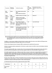
...magnetic Yes replaceable, media, various sizes in the system supports S3 state. The OS does not save any component on the memory (DDR3L). cache or memory. Dell systems will be SSD (solid state flash drive) Low level format mSATA WWAN1 mSATA module would share Yes NA with WWAN ...if power is called "suspend to disk" state or "hibernate" mode. In this state, the dynamic RAM is read/write by Dell Latitude™ 3330: Model Number S0 S1 S3 S4 S5 Dell Latitude™ X X X X X 3330 S1 state is maintained. There is the shut off state.
...magnetic Yes replaceable, media, various sizes in the system supports S3 state. The OS does not save any component on the memory (DDR3L). cache or memory. Dell systems will be SSD (solid state flash drive) Low level format mSATA WWAN1 mSATA module would share Yes NA with WWAN ...if power is called "suspend to disk" state or "hibernate" mode. In this state, the dynamic RAM is read/write by Dell Latitude™ 3330: Model Number S0 S1 S3 S4 S5 Dell Latitude™ X X X X X 3330 S1 state is maintained. There is the shut off state.


