Setup Guide
Page 5
Contents Setting Up Your Inspiron Laptop 5 Before Setting Up Your Computer 5 Connect the AC Adapter 6 Connect the Network ... Wireless (Optional 14 Set Up Wireless Display (Optional 16 Connect to the Internet (Optional 17 Using Your Inspiron Laptop 20 Right View Features 20 Left View Features 22 Back View Features 26 Front View Features... 28 Status Lights and Indicators 30 Disabling Battery Charging 31 Computer Base and Keyboard Features 32 Touch Pad Gestures 36 Multimedia Control Keys 38 Using the Optical Drive 40 Display Features 42 ...
Contents Setting Up Your Inspiron Laptop 5 Before Setting Up Your Computer 5 Connect the AC Adapter 6 Connect the Network ... Wireless (Optional 14 Set Up Wireless Display (Optional 16 Connect to the Internet (Optional 17 Using Your Inspiron Laptop 20 Right View Features 20 Left View Features 22 Back View Features 26 Front View Features... 28 Status Lights and Indicators 30 Disabling Battery Charging 31 Computer Base and Keyboard Features 32 Touch Pad Gestures 36 Multimedia Control Keys 38 Using the Optical Drive 40 Display Features 42 ...

Service Manual
Page 4
Replacing the Memory Module(s 20 6 Optical Drive 23 Removing the Optical Drive 23 Replacing the Optical Drive 24 7 Keyboard 27 Removing the Keyboard 27 Replacing the Keyboard 29 8 Palm-Rest Assembly 31 Removing the Palm-Rest Assembly 31 Replacing the Palm-Rest Assembly 34 9 Wireless Mini-Card(s 37 Removing the Mini-Card(s 37 Replacing the Mini-Card(s 39 10 Display 41 Display Assembly 41 Removing the Display Assembly 41 Replacing the Display Assembly 43 Display Bezel 44 4 Contents
Replacing the Memory Module(s 20 6 Optical Drive 23 Removing the Optical Drive 23 Replacing the Optical Drive 24 7 Keyboard 27 Removing the Keyboard 27 Replacing the Keyboard 29 8 Palm-Rest Assembly 31 Removing the Palm-Rest Assembly 31 Replacing the Palm-Rest Assembly 34 9 Wireless Mini-Card(s 37 Removing the Mini-Card(s 37 Replacing the Mini-Card(s 39 10 Display 41 Display Assembly 41 Removing the Display Assembly 41 Replacing the Display Assembly 43 Display Bezel 44 4 Contents
Service Manual
Page 27
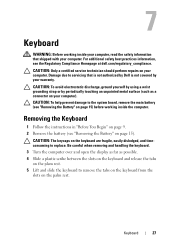
... palm rest. For additional safety best practices information, see "Removing the Battery" on the keyboard are fragile, easily dislodged, and timeconsuming to replace. 7 Keyboard WARNING: Before working inside your computer, read the safety information that is not authorized by Dell is not covered by periodically touching an unpainted metal surface (such as possible. 4 Slide...
... palm rest. For additional safety best practices information, see "Removing the Battery" on the keyboard are fragile, easily dislodged, and timeconsuming to replace. 7 Keyboard WARNING: Before working inside your computer, read the safety information that is not authorized by Dell is not covered by periodically touching an unpainted metal surface (such as possible. 4 Slide...
Service Manual
Page 28
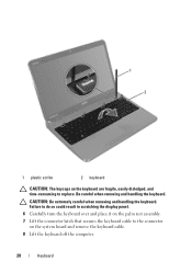
Be careful when removing and handling the keyboard. Failure to do so could result in scratching the display panel. 6 Carefully turn the keyboard over and place it on the system board and remove the keyboard cable. 8 Lift the keyboard off the computer. 28 Keyboard CAUTION: Be extremely careful when removing and handling the keyboard. 1 2 1 plastic scribe 2 keyboard CAUTION: The keycaps on the keyboard are fragile, easily dislodged, and time-consuming to the connector on the palm rest assembly. 7 Lift the connector latch that secures the keyboard cable to replace.
Be careful when removing and handling the keyboard. Failure to do so could result in scratching the display panel. 6 Carefully turn the keyboard over and place it on the system board and remove the keyboard cable. 8 Lift the keyboard off the computer. 28 Keyboard CAUTION: Be extremely careful when removing and handling the keyboard. 1 2 1 plastic scribe 2 keyboard CAUTION: The keycaps on the keyboard are fragile, easily dislodged, and time-consuming to the connector on the palm rest assembly. 7 Lift the connector latch that secures the keyboard cable to replace.
Service Manual
Page 29
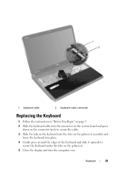
Keyboard 29 1 2 1 keyboard cable 2 keyboard-cable connector Replacing the Keyboard 1 Follow the instructions in "Before You Begin" on page 9. 2 Slide the keyboard cable into the connector on the system board and press down on the connector latch to secure the cable. 3 Slide the tabs on the keyboard into the slots on the palm-rest assembly and lower the keyboard into place. 4 Gently press around the edges of the keyboard and slide it upwards to secure the keyboard under the tabs on the palm rest. 5 Close the display and turn the computer over.
Keyboard 29 1 2 1 keyboard cable 2 keyboard-cable connector Replacing the Keyboard 1 Follow the instructions in "Before You Begin" on page 9. 2 Slide the keyboard cable into the connector on the system board and press down on the connector latch to secure the cable. 3 Slide the tabs on the keyboard into the slots on the palm-rest assembly and lower the keyboard into place. 4 Gently press around the edges of the keyboard and slide it upwards to secure the keyboard under the tabs on the palm rest. 5 Close the display and turn the computer over.
Service Manual
Page 30
6 Replace the battery (see "Replacing the Battery" on page 16). 30 Keyboard
6 Replace the battery (see "Replacing the Battery" on page 16). 30 Keyboard

Service Manual
Page 34
1 2 1 plastic scribe 2 palm-rest assembly Replacing the Palm-Rest Assembly 1 Follow the instructions in "Before You Begin" on page 9. 2 Align the tabs on the palm rest assembly with the slots on the computer base and gently snap the palm rest assembly in place. 3 Slide the touch-pad cable, power-button board cable, and hot-key board cable into the connectors on the system board and press down on the connector latches to secure them. 4 Replace the four screws on the palm-rest assembly. 5 Replace the keyboard (see "Replacing the Keyboard" on page 29). 34 Palm-Rest Assembly
1 2 1 plastic scribe 2 palm-rest assembly Replacing the Palm-Rest Assembly 1 Follow the instructions in "Before You Begin" on page 9. 2 Align the tabs on the palm rest assembly with the slots on the computer base and gently snap the palm rest assembly in place. 3 Slide the touch-pad cable, power-button board cable, and hot-key board cable into the connectors on the system board and press down on the connector latches to secure them. 4 Replace the four screws on the palm-rest assembly. 5 Replace the keyboard (see "Replacing the Keyboard" on page 29). 34 Palm-Rest Assembly


