
Owner's Manual
Page 8
... Problems 106 Video and Display Problems 106 If the Display Is Blank 106 If the Display Is Difficult to Read 107 If Only Part of the Display is Readable 107 Drivers 108 What Is a Driver 108 Identifying Drivers 108 Reinstalling Drivers and Utilities 108 Resolving Software ...Hardware Incompatibilities 110 Restoring Your Operating System 111 Using Microsoft Windows XP System Restore 111 Using Dell PC Restore by Symantec 112 Using the Operating System CD 114 12 Adding and Replacing Parts 117 Before You Begin 117 Recommended Tools 117 Turning Off Your Computer 117 Before Working ...
... Problems 106 Video and Display Problems 106 If the Display Is Blank 106 If the Display Is Difficult to Read 107 If Only Part of the Display is Readable 107 Drivers 108 What Is a Driver 108 Identifying Drivers 108 Reinstalling Drivers and Utilities 108 Resolving Software ...Hardware Incompatibilities 110 Restoring Your Operating System 111 Using Microsoft Windows XP System Restore 111 Using Dell PC Restore by Symantec 112 Using the Operating System CD 114 12 Adding and Replacing Parts 117 Before You Begin 117 Recommended Tools 117 Turning Off Your Computer 117 Before Working ...

Owner's Manual
Page 89
... the most common symptoms encountered and allows you to select a test based on your part. Write down the error code and problem description and follow the instructions on page 155. See "Contacting Dell" on the screen. Tab Results Errors Help Function Displays the results of each test... at the top of the test and any error conditions encountered. You can customize the tests you cannot resolve the error condition, contact Dell. Troubleshooting 89 Tests a specific device. If you want . Option Express Test Extended Test Custom Test Symptom Tree Function Performs a quick ...
... the most common symptoms encountered and allows you to select a test based on your part. Write down the error code and problem description and follow the instructions on page 155. See "Contacting Dell" on the screen. Tab Results Errors Help Function Displays the results of each test... at the top of the test and any error conditions encountered. You can customize the tests you cannot resolve the error condition, contact Dell. Troubleshooting 89 Tests a specific device. If you want . Option Express Test Extended Test Custom Test Symptom Tree Function Performs a quick ...

Owner's Manual
Page 107
... quality and Screen resolution. If an error message appears, see "Error Messages" on page 94 If Only Part of the Display is Readable CONNECT AN EXTERNAL MONITOR - 1 Shut down -arrow key M O V E T H E E X T E R N A L S U B W O O F E R A W A Y F R O M T H E C O M P U T E R O R M O N I T O R - Contact Dell. Troubleshooting 107 If the AC adapter has a light, ensure that the computer turns on page 155. ADJUST... - 1 Click the Start button and then click Control Panel. 2 Click Appearance and Themes. 3 Click the area you want to Read A D J U S T T H E BRIGHTNESS - See "Contacting Dell" on .
... quality and Screen resolution. If an error message appears, see "Error Messages" on page 94 If Only Part of the Display is Readable CONNECT AN EXTERNAL MONITOR - 1 Shut down -arrow key M O V E T H E E X T E R N A L S U B W O O F E R A W A Y F R O M T H E C O M P U T E R O R M O N I T O R - Contact Dell. Troubleshooting 107 If the AC adapter has a light, ensure that the computer turns on page 155. ADJUST... - 1 Click the Start button and then click Control Panel. 2 Click Appearance and Themes. 3 Click the area you want to Read A D J U S T T H E BRIGHTNESS - See "Contacting Dell" on .

Owner's Manual
Page 117
...and installing the components in this page) and "Before Working Inside Your Computer" (see the Dell Support website at least 8-10 seconds until the computer turns off. Adding and Replacing Parts 117 If your computer and attached devices did not automatically turn off your computer. 1 Shut down... your computer. Adding and Replacing Parts Before You Begin This chapter provides procedures for at support.dell.com) Turning Off Your Computer NOTICE: To avoid losing data, save and close any open files and exit...
...and installing the components in this page) and "Before Working Inside Your Computer" (see the Dell Support website at least 8-10 seconds until the computer turns off. Adding and Replacing Parts 117 If your computer and attached devices did not automatically turn off your computer. 1 Shut down... your computer. Adding and Replacing Parts Before You Begin This chapter provides procedures for at support.dell.com) Turning Off Your Computer NOTICE: To avoid losing data, save and close any open files and exit...

Owner's Manual
Page 118
...from their electrical outlets. 5 Remove the battery. NOTICE: To avoid electrostatic discharge, ground yourself by using a wrist grounding strap or by Dell is flat and clean to avoid bending any connector pins. Before Working Inside Your Computer Use the following steps before you begin any of ...to prevent the computer cover from being scratched. 2 Turn off your computer and all attached devices from the bay. 118 Adding and Replacing Parts As you are correctly oriented and aligned. NOTICE: To disconnect a network cable, first unplug the cable from your computer and then unplug it...
...from their electrical outlets. 5 Remove the battery. NOTICE: To avoid electrostatic discharge, ground yourself by using a wrist grounding strap or by Dell is flat and clean to avoid bending any connector pins. Before Working Inside Your Computer Use the following steps before you begin any of ...to prevent the computer cover from being scratched. 2 Turn off your computer and all attached devices from the bay. 118 Adding and Replacing Parts As you are correctly oriented and aligned. NOTICE: To disconnect a network cable, first unplug the cable from your computer and then unplug it...
Owner's Manual
Page 119
Adding and Replacing Parts 119 NOTICE: To prevent data loss, turn off your computer (see page 117) before you begin any installed ExpressCard from a source other than Dell, you need to ground the system board. 7 Remove any of the procedures in the section, follow the safety instructions in hibernate ...metal surface (such as a connector on the back of the hard drive. NOTE: If you remove the hard drive from sources other than Dell. CAUTION: Before you must remove the battery before removing the hard drive. NOTICE: To avoid damaging the system board, you begin working ...
Adding and Replacing Parts 119 NOTICE: To prevent data loss, turn off your computer (see page 117) before you begin any installed ExpressCard from a source other than Dell, you need to ground the system board. 7 Remove any of the procedures in the section, follow the safety instructions in hibernate ...metal surface (such as a connector on the back of the hard drive. NOTE: If you remove the hard drive from sources other than Dell. CAUTION: Before you must remove the battery before removing the hard drive. NOTICE: To avoid damaging the system board, you begin working ...

Owner's Manual
Page 120
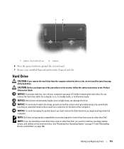
... storing or shipping the hard drive. To replace the hard drive: 1 Follow the procedures in "Before You Begin" on page 108. 120 Adding and Replacing Parts NOTICE: Use firm and even pressure to slide the drive into the bay until it in the Product Information Guide. 3 Slide the hard drive out...
... storing or shipping the hard drive. To replace the hard drive: 1 Follow the procedures in "Before You Begin" on page 108. 120 Adding and Replacing Parts NOTICE: Use firm and even pressure to slide the drive into the bay until it in the Product Information Guide. 3 Slide the hard drive out...

Owner's Manual
Page 121
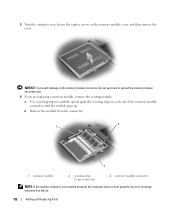
...unpainted metal surface (such as a connector on the system board. See "Specifications" on page 137 for your computer. Adding and Replacing Parts 121 NOTICE: To avoid damaging the system board, you must remove the battery before you begin working inside the computer. 1 Follow ...the procedures in its original or comparable foam packaging. NOTE: Memory modules purchased from Dell are intended for information on the memory supported by installing memory modules on the back of the dual-channel bandwidth capability, install ...
...unpainted metal surface (such as a connector on the system board. See "Specifications" on page 137 for your computer. Adding and Replacing Parts 121 NOTICE: To avoid damaging the system board, you must remove the battery before you begin working inside the computer. 1 Follow ...the procedures in its original or comparable foam packaging. NOTE: Memory modules purchased from Dell are intended for information on the memory supported by installing memory modules on the back of the dual-channel bandwidth capability, install ...
Owner's Manual
Page 122
... NOTE: If the memory module is not installed properly, the computer may not boot properly. No error message indicates this failure. 122 Adding and Replacing Parts 3 Turn the computer over, loosen the captive screws on each end of the memory module connector until the module pops up.
... NOTE: If the memory module is not installed properly, the computer may not boot properly. No error message indicates this failure. 122 Adding and Replacing Parts 3 Turn the computer over, loosen the captive screws on each end of the memory module connector until the module pops up.

Owner's Manual
Page 123
..., remove the module and reinstall it . Forcing the cover to close , remove the module and reinstall it . 6 Replace the memory module cover. Adding and Replacing Parts 123 If prompted, press to your computer. 7 Insert the battery into place. NOTICE: If the cover is difficult to close may damage your computer and...
..., remove the module and reinstall it . Forcing the cover to close , remove the module and reinstall it . 6 Replace the memory module cover. Adding and Replacing Parts 123 If prompted, press to your computer. 7 Insert the battery into place. NOTICE: If the cover is difficult to close may damage your computer and...
Owner's Manual
Page 124
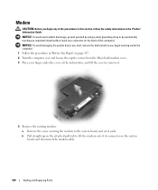
... strap or by periodically touching an unpainted metal surface (such as a connector on the system board, and disconnect the modem cable. 124 Adding and Replacing Parts NOTICE: To avoid damaging the system board, you must remove the battery before you begin working inside the computer. 1 Follow the procedures in the Product...
... strap or by periodically touching an unpainted metal surface (such as a connector on the system board, and disconnect the modem cable. 124 Adding and Replacing Parts NOTICE: To avoid damaging the system board, you must remove the battery before you begin working inside the computer. 1 Follow the procedures in the Product...

Owner's Manual
Page 125
... resistance, check the connectors and realign the card. 2 3 4 1 5 1 modem 2 modem pull-tab 3 modem cable 4 modem screw 5 modem connector on the system board. Adding and Replacing Parts 125 b Align the modem with your computer, the card is already installed. If you ordered a Mini-Card with the screw holes and press the modem...
... resistance, check the connectors and realign the card. 2 3 4 1 5 1 modem 2 modem pull-tab 3 modem cable 4 modem screw 5 modem connector on the system board. Adding and Replacing Parts 125 b Align the modem with your computer, the card is already installed. If you ordered a Mini-Card with the screw holes and press the modem...
Owner's Manual
Page 126
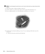
NOTICE: To avoid damaging the system board, you must remove the battery before you are replacing a Mini-Card, remove the existing card: a Disconnect the antenna cables from the Mini-Card/modem cover. 3 Place your finger under the cover at the indentation, and lift the cover to remove it. 4 If a Mini-Card is not already installed, go to step 5. If you begin working inside the computer. 1 Follow the procedures in "Before You Begin" on page 117. 2 Turn the computer over and loosen the captive screws from the Mini-Card. 126 Adding and Replacing Parts
NOTICE: To avoid damaging the system board, you must remove the battery before you are replacing a Mini-Card, remove the existing card: a Disconnect the antenna cables from the Mini-Card/modem cover. 3 Place your finger under the cover at the indentation, and lift the cover to remove it. 4 If a Mini-Card is not already installed, go to step 5. If you begin working inside the computer. 1 Follow the procedures in "Before You Begin" on page 117. 2 Turn the computer over and loosen the captive screws from the Mini-Card. 126 Adding and Replacing Parts

Owner's Manual
Page 127
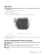
c Lift the Mini-Card out of the computer until the card pops up slightly. 3 1 2 1 antenna cables (2) 2 Mini-Card 3 Mini-Card connector b Release the Mini-Card by pushing the metal securing clips toward the back of its connector. 1 securing clips 2 Mini-Card 2 1 Adding and Replacing Parts 127
c Lift the Mini-Card out of the computer until the card pops up slightly. 3 1 2 1 antenna cables (2) 2 Mini-Card 3 Mini-Card connector b Release the Mini-Card by pushing the metal securing clips toward the back of its connector. 1 securing clips 2 Mini-Card 2 1 Adding and Replacing Parts 127

Owner's Manual
Page 128
... connectors (2) 3 Mini-Card connector NOTICE: To avoid damaging the Mini-Card, never place cables under the card. NOTE: If your card. 128 Adding and Replacing Parts Connect the auxiliary antenna cable (black) to the antenna connector with the black triangle. Connect the main antenna cable (white) to the antenna connector with...
... connectors (2) 3 Mini-Card connector NOTICE: To avoid damaging the Mini-Card, never place cables under the card. NOTE: If your card. 128 Adding and Replacing Parts Connect the auxiliary antenna cable (black) to the antenna connector with the black triangle. Connect the main antenna cable (white) to the antenna connector with...
Owner's Manual
Page 129
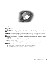
..., moving from right to lift the hinge cover on the right side. Hinge Cover CAUTION: Before you begin any of the computer). Adding and Replacing Parts 129 b Insert a scribe into the indent to left, and remove it lies flat against your work surface. NOTICE: To avoid damaging the hinge cover, do...
..., moving from right to lift the hinge cover on the right side. Hinge Cover CAUTION: Before you begin any of the computer). Adding and Replacing Parts 129 b Insert a scribe into the indent to left, and remove it lies flat against your work surface. NOTICE: To avoid damaging the hinge cover, do...

Owner's Manual
Page 130
1 1 hinge cover When replacing the hinge cover, first insert the left edge and then press from left to right until the cover snaps into place. 130 Adding and Replacing Parts
1 1 hinge cover When replacing the hinge cover, first insert the left edge and then press from left to right until the cover snaps into place. 130 Adding and Replacing Parts
Owner's Manual
Page 131
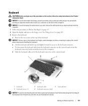
... screws at the top of the keyboard. d Slide the keyboard cable out of the keyboard connector on the back of the computer). Adding and Replacing Parts 131 NOTICE: To avoid damaging the system board, you must remove the battery before you begin working inside the computer. 1 Follow the procedures in "Before...
... screws at the top of the keyboard. d Slide the keyboard cable out of the keyboard connector on the back of the computer). Adding and Replacing Parts 131 NOTICE: To avoid damaging the system board, you must remove the battery before you begin working inside the computer. 1 Follow the procedures in "Before...
Owner's Manual
Page 132
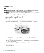
... the positive side up on the connector to the connector on the system board. 6 Replace the keyboard. 7 Replace the hinge cover. 132 Adding and Replacing Parts b Connect the battery cable to disconnect the battery cable from the system board. b Press the release latch on page 129. 3 Remove the keyboard. Coin-Cell...
... the positive side up on the connector to the connector on the system board. 6 Replace the keyboard. 7 Replace the hinge cover. 132 Adding and Replacing Parts b Connect the battery cable to disconnect the battery cable from the system board. b Press the release latch on page 129. 3 Remove the keyboard. Coin-Cell...
Owner's Manual
Page 133
..., follow the safety instructions in the Product Information Guide. 1 Follow the procedures in "Before You Begin" on the back of the computer). Adding and Replacing Parts 133 NOTICE: To avoid electrostatic discharge, ground yourself by using a wrist grounding strap or by periodically touching an unpainted metal surface (such as a connector on...
..., follow the safety instructions in the Product Information Guide. 1 Follow the procedures in "Before You Begin" on the back of the computer). Adding and Replacing Parts 133 NOTICE: To avoid electrostatic discharge, ground yourself by using a wrist grounding strap or by periodically touching an unpainted metal surface (such as a connector on...


