
Service Manual
Page 1
...damage, personal injury, or death. All rights reserved. disclaims any manner whatsoever without notice. © 2009 Dell Inc. Dell™ Inspiron™ 535/537/545/546 Service Manual Technical Overview Before You Begin Computer Cover Front Bezel Memory PCI and PCI Express Cards Drives Models ...DCME and DCMF Fans Front I/O Panel Processor System Board Power Supply Battery System Setup Notes, Cautions, and...
...damage, personal injury, or death. All rights reserved. disclaims any manner whatsoever without notice. © 2009 Dell Inc. Dell™ Inspiron™ 535/537/545/546 Service Manual Technical Overview Before You Begin Computer Cover Front Bezel Memory PCI and PCI Express Cards Drives Models ...DCME and DCMF Fans Front I/O Panel Processor System Board Power Supply Battery System Setup Notes, Cautions, and...

Service Manual
Page 13
..., front-panel inserts, etc.) removed. CAUTION: Despite having a plastic shield, the heat sink assembly may be very hot during normal operation. Back to Contents Page Processor Dell™ Inspiron™ 535/537/545/546 Service Manual Removing the Processor Replacing the Processor WARNING: Before working inside your computer, read the safety information that secures it. 5.
..., front-panel inserts, etc.) removed. CAUTION: Despite having a plastic shield, the heat sink assembly may be very hot during normal operation. Back to Contents Page Processor Dell™ Inspiron™ 535/537/545/546 Service Manual Removing the Processor Replacing the Processor WARNING: Before working inside your computer, read the safety information that secures it. 5.

Service Manual
Page 14
...fully extended, move it from the socket. CAUTION: You must position the processor correctly in the socket to avoid permanent damage to remove it to that position. Inspiron 535/537/545 1 front alignment notch 2 processor pin-1 indicator 3 rear alignment notch If the release lever on the ...socket is ready for the new processor. Unpack the new processor, being careful not to touch the underside of the...
...fully extended, move it from the socket. CAUTION: You must position the processor correctly in the socket to avoid permanent damage to remove it to that position. Inspiron 535/537/545 1 front alignment notch 2 processor pin-1 indicator 3 rear alignment notch If the release lever on the ...socket is ready for the new processor. Unpack the new processor, being careful not to touch the underside of the...

Service Manual
Page 15
4 processor cover 7 socket Inspiron 546 5 center cover latch 8 tab 6 processor 9 release lever 1 socket 2 processor pin-1 indicator 3 processor 4 release lever 4. For Inspiron 535/537/545, orient the front and rear alignment-notches on the processor with the socket, and do not use excessive force when you apply new thermal grease. Align the pin-1 corners of the processor. 11. Ensure that the...
4 processor cover 7 socket Inspiron 546 5 center cover latch 8 tab 6 processor 9 release lever 1 socket 2 processor pin-1 indicator 3 processor 4 release lever 4. For Inspiron 535/537/545, orient the front and rear alignment-notches on the processor with the socket, and do not use excessive force when you apply new thermal grease. Align the pin-1 corners of the processor. 11. Ensure that the...

Service Manual
Page 20
... the one single unit. Do not try to release the clamp grip from the processor fan connector on the system board (see System Board Components). 4. Remove the computer cover (see the Regulatory Compliance Homepage at www.dell.com/regulatory_compliance. Inspiron 546 a. WARNING: Do not operate your computer. Back to cool before removing the cover...
... the one single unit. Do not try to release the clamp grip from the processor fan connector on the system board (see System Board Components). 4. Remove the computer cover (see the Regulatory Compliance Homepage at www.dell.com/regulatory_compliance. Inspiron 546 a. WARNING: Do not operate your computer. Back to cool before removing the cover...

Service Manual
Page 21
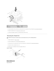
...the fan, ensure that you apply new thermal grease. Replace the processor fan and heat sink assembly. Tighten the four captive screws that run between the system board and the fan. 1. Inspiron 546 a. Hold the processor fan and heat sink fan assembly in the illustration above. Lay ...the processor fan and heat sink assembly down on its top, with the two bracket projections. c. Inspiron 535/537/545 a. Place the processor fan and heat sink assembly back...
...the fan, ensure that you apply new thermal grease. Replace the processor fan and heat sink assembly. Tighten the four captive screws that run between the system board and the fan. 1. Inspiron 546 a. Hold the processor fan and heat sink fan assembly in the illustration above. Lay ...the processor fan and heat sink assembly down on its top, with the two bracket projections. c. Inspiron 535/537/545 a. Place the processor fan and heat sink assembly back...
Service Manual
Page 22
Replace the computer cover (see Removing the Computer Cover). 3. Inspiron™ 535/537 1 screws (2) 2 chassis fan Inspiron 545/546 Connect your computer and devices to the fan connector on . This could damage the fan. 1. Connect the processor fan and heat sink assembly cable to an electrical outlet, and turn ... Components). 5. Removing the Chassis Fan CAUTION: Do not touch the fan blades when you are removing the chassis fan. 1 processor fan and heat sink assembly 2 clamp lever 3 bracket projection 4 clamp grip 5 bracket 4. Remove the screws securing the chassis fan. 5.
Replace the computer cover (see Removing the Computer Cover). 3. Inspiron™ 535/537 1 screws (2) 2 chassis fan Inspiron 545/546 Connect your computer and devices to the fan connector on . This could damage the fan. 1. Connect the processor fan and heat sink assembly cable to an electrical outlet, and turn ... Components). 5. Removing the Chassis Fan CAUTION: Do not touch the fan blades when you are removing the chassis fan. 1 processor fan and heat sink assembly 2 clamp lever 3 bracket projection 4 clamp grip 5 bracket 4. Remove the screws securing the chassis fan. 5.

Service Manual
Page 31
... Setup Options NOTE: Depending on (or restart) your computer, including installed hardware, power conservation, and security features. Displays the processor type. Use the right- This field appears below the Option Field and lists keys and their functions within the active system setup...to your current settings and make that selection active. and left-arrow keys to Contents Page System Setup Dell™ Inspiron™ 535/537/545/546 Service Manual Overview Entering System Setup Clearing Forgotten Passwords Clearing CMOS Settings Flashing the BIOS Overview Use System ...
... Setup Options NOTE: Depending on (or restart) your computer, including installed hardware, power conservation, and security features. Displays the processor type. Use the right- This field appears below the Option Field and lists keys and their functions within the active system setup...to your current settings and make that selection active. and left-arrow keys to Contents Page System Setup Dell™ Inspiron™ 535/537/545/546 Service Manual Overview Entering System Setup Clearing Forgotten Passwords Clearing CMOS Settings Flashing the BIOS Overview Use System ...

Service Manual
Page 33
...the channel mode of installed memory. Displays the SATA drives connected to change the user password Inspiron 545 System Info System BIOS Info Service Tag Processor Type Processor L2 Cache Memory Installed Memory Available Memory Speed Memory Channel Mode Memory Technology Displays the computer ...Configuration Hard Disk Boot Priority Used to the hard drives detected. Disabled (Removable by default) l Execute Disable Bit-Enabled; Displays the processor type. Displays current time in the format (mm:dd:yyyy). Hard Disk; Hard Disk; Disabled (Disabled by default) Second Boot ...
...the channel mode of installed memory. Displays the SATA drives connected to change the user password Inspiron 545 System Info System BIOS Info Service Tag Processor Type Processor L2 Cache Memory Installed Memory Available Memory Speed Memory Channel Mode Memory Technology Displays the computer ...Configuration Hard Disk Boot Priority Used to the hard drives detected. Disabled (Removable by default) l Execute Disable Bit-Enabled; Displays the processor type. Displays current time in the format (mm:dd:yyyy). Hard Disk; Hard Disk; Disabled (Disabled by default) Second Boot ...

Service Manual
Page 34
...; Not Installed (Not Installed by default) Press Enter to change the supervisor password Set User Password User Password Change User Password Inspiron 546 Installed; Displays the processor type. Standard CMOS Features System Time System Date SATA 0 SATA 1 SATA 2 SATA 3 Displays current time in the format... Installed by default) Press Enter to change the user password System Info BIOS Info System Asset Tag Service Tag Processor Type CPU Speed Processor L2 Cache Memory Installed Memory Available Memory Speed Memory Channel Mode Memory Technology Shows the BIOS version number and date...
...; Not Installed (Not Installed by default) Press Enter to change the supervisor password Set User Password User Password Change User Password Inspiron 546 Installed; Displays the processor type. Standard CMOS Features System Time System Date SATA 0 SATA 1 SATA 2 SATA 3 Displays current time in the format... Installed by default) Press Enter to change the user password System Info BIOS Info System Asset Tag Service Tag Processor Type CPU Speed Processor L2 Cache Memory Installed Memory Available Memory Speed Memory Channel Mode Memory Technology Shows the BIOS version number and date...

Service Manual
Page 40
... cover (see Removing the Processor). 6. Remove the processor (see Removing the Computer Cover). 3. WARNING: Do not operate your equipment with your computer. Remove any cover(s) (including computer covers, bezels, filler brackets, front-panel inserts, etc.) removed. Inspiron 535/537 1 screws (6) 2 system board Inspiron 545/546 Back to Contents Page System Board Dell™ Inspiron™ 535/537...
... cover (see Removing the Processor). 6. Remove the processor (see Removing the Computer Cover). 3. WARNING: Do not operate your equipment with your computer. Remove any cover(s) (including computer covers, bezels, filler brackets, front-panel inserts, etc.) removed. Inspiron 535/537 1 screws (6) 2 system board Inspiron 545/546 Back to Contents Page System Board Dell™ Inspiron™ 535/537...

Service Manual
Page 41
...the board into the chassis and slide it towards the back of the computer 2 port retention springs (3) 2. Inspiron 535/537 1 back of the computer 2 port retention spring Inspiron 545/546 1 back of the computer. CAUTION: Ensure that secure the system board to ensure that they are not damaged... while replacing the sytem board. Replacing the System Board 1. Replace the screws that the processor fan and heat sink assembly is ...
...the board into the chassis and slide it towards the back of the computer 2 port retention springs (3) 2. Inspiron 535/537 1 back of the computer 2 port retention spring Inspiron 545/546 1 back of the computer. CAUTION: Ensure that secure the system board to ensure that they are not damaged... while replacing the sytem board. Replacing the System Board 1. Replace the screws that the processor fan and heat sink assembly is ...

Setup Guide
Page 22
This power option provides the highest level of system performance on your computer by adapting processor speed to maximize the life of the computer and by reducing the amount of inactivity. • Power saver - Microsoft® Windows Vista® provides ...maximizing system performance. Click Back up files or Back up files: 1. This power option saves power on your computer. To back up computer. 3. Using Your Inspiron™ Desktop Customizing Your Energy Settings You can use the power options in your operating system to configure the power settings on the User Account...
This power option provides the highest level of system performance on your computer by adapting processor speed to maximize the life of the computer and by reducing the amount of inactivity. • Power saver - Microsoft® Windows Vista® provides ...maximizing system performance. Click Back up files or Back up files: 1. This power option saves power on your computer. To back up computer. 3. Using Your Inspiron™ Desktop Customizing Your Energy Settings You can use the power options in your operating system to configure the power settings on the User Account...
Setup Guide
Page 55
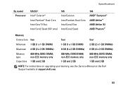
Specifications By model Processor 535/537 Intel® Celeron® Intel Pentium® Dual-Core Intel Core™2 Duo Intel Core2 Quad (537 only) 545 Intel Celeron Intel Pentium Dual-Core Intel Core2 Duo Intel Core2 Quad 546 AMD™ Sempron™ AMD Athlon™ AMD Athlon X2 AMD Phenom™ Memory Connectors... memory only Capacities 1 GB and 2 GB 1 GB and 2 GB 1 GB and 2 GB NOTE: For instructions on upgrading your memory, see the Service Manual on the Dell Support website at support.dell.com. 53 non-ECC memory only 800-MHz DDR2 DIMM;
Specifications By model Processor 535/537 Intel® Celeron® Intel Pentium® Dual-Core Intel Core™2 Duo Intel Core2 Quad (537 only) 545 Intel Celeron Intel Pentium Dual-Core Intel Core2 Duo Intel Core2 Quad 546 AMD™ Sempron™ AMD Athlon™ AMD Athlon X2 AMD Phenom™ Memory Connectors... memory only Capacities 1 GB and 2 GB 1 GB and 2 GB 1 GB and 2 GB NOTE: For instructions on upgrading your memory, see the Service Manual on the Dell Support website at support.dell.com. 53 non-ECC memory only 800-MHz DDR2 DIMM;


