
Service Manual
Page 6
Removing the power-button module 56 Prerequisites 56 Procedure 56 Replacing the power-button module 58 Procedure 58 Post-requisites 58 Removing the chassis fan 59 Prerequisites 59 Procedure 59 Replacing the chassis fan 61 Procedure 61 Post-requisites 61 Removing the power-supply unit 62 Prerequisites 62 Procedure 62 Replacing the power-supply unit 65 Procedure 65 Post-requisites 65 Removing the processor fan 66 Prerequisites 66 Procedure 66 Replacing the processor fan 68 Procedure 68 Post-requisites 68 6
Removing the power-button module 56 Prerequisites 56 Procedure 56 Replacing the power-button module 58 Procedure 58 Post-requisites 58 Removing the chassis fan 59 Prerequisites 59 Procedure 59 Replacing the chassis fan 61 Procedure 61 Post-requisites 61 Removing the power-supply unit 62 Prerequisites 62 Procedure 62 Replacing the power-supply unit 65 Procedure 65 Post-requisites 65 Removing the processor fan 66 Prerequisites 66 Procedure 66 Replacing the processor fan 68 Procedure 68 Post-requisites 68 6

Service Manual
Page 14
... drive Hard-drive bracket #6-32xL3.6 2 Optical drive Chassis #6-32xL3.6 1 Optical drive Drive cage M2xL2 3 Wireless card System board M2xL3.5 1 Processor fan Processor heat sink M6xL10 4 Power-supply unit Chassis #6-32xL6.35 3 Front I/O bracket Chassis #6-32xL6.35 1 System board Chassis #6-32xL6.35 6 14 Screw list Component Secured to the computer.
... drive Hard-drive bracket #6-32xL3.6 2 Optical drive Chassis #6-32xL3.6 1 Optical drive Drive cage M2xL2 3 Wireless card System board M2xL3.5 1 Processor fan Processor heat sink M6xL10 4 Power-supply unit Chassis #6-32xL6.35 3 Front I/O bracket Chassis #6-32xL6.35 1 System board Chassis #6-32xL6.35 6 14 Screw list Component Secured to the computer.

Service Manual
Page 15
Inside view of your computer 1 system board 3 processor fan and heat-sink assembly 5 drive cage 7 power-supply unit 2 memory modules 4 2.5-inch hard-drive assembly 6 chassis fan 15
Inside view of your computer 1 system board 3 processor fan and heat-sink assembly 5 drive cage 7 power-supply unit 2 memory modules 4 2.5-inch hard-drive assembly 6 chassis fan 15

Service Manual
Page 17
1 power-button cable connector 2 wireless-card slot 3 coin-cell battery 4 hard drive and optical drive powercable connector 5 chassis-fan cable connector 6 SATA 0 connector 7 SATA 2 connector 8 power-supply unit cable connector 9 SATA 1 connector 10 memory-module slots (2) 11 graphics card slot (PCIe x16) 12 PCI-card slot(PCIe x1) 13 CMOS jumper 14 password jumper 15 service-mode jumper 16 processor socket 17 power-supply unit cable connector 18 processor-fan cable connector 17
1 power-button cable connector 2 wireless-card slot 3 coin-cell battery 4 hard drive and optical drive powercable connector 5 chassis-fan cable connector 6 SATA 0 connector 7 SATA 2 connector 8 power-supply unit cable connector 9 SATA 1 connector 10 memory-module slots (2) 11 graphics card slot (PCIe x16) 12 PCI-card slot(PCIe x1) 13 CMOS jumper 14 password jumper 15 service-mode jumper 16 processor socket 17 power-supply unit cable connector 18 processor-fan cable connector 17

Service Manual
Page 62
...see the Regulatory Compliance home page at www.dell.com/ regulatory_compliance. Prerequisites 1 Remove the computer cover. 2 Remove the front bezel. 3 Follow the procedure from the system board. 62 Procedure 1 Press the securing clip and disconnect the power-supply unit cable (ATX2) from the system ...board. 2 Press the securing clip and disconnect the power-supply unit cable (ATX1) from step 1 to step 5 in "Removing the optical drive". Removing the power-supply unit WARNING: Before working inside your...
...see the Regulatory Compliance home page at www.dell.com/ regulatory_compliance. Prerequisites 1 Remove the computer cover. 2 Remove the front bezel. 3 Follow the procedure from the system board. 62 Procedure 1 Press the securing clip and disconnect the power-supply unit cable (ATX2) from the system ...board. 2 Press the securing clip and disconnect the power-supply unit cable (ATX1) from step 1 to step 5 in "Removing the optical drive". Removing the power-supply unit WARNING: Before working inside your...

Service Manual
Page 63
3 Note the power-supply unit cable routing and remove the power-supply unit cable from the routing guides on the chassis. 4 Remove the three screws (#6-32xL6.35) that secure the power-supply unit to the chassis. 5 Press the clamp and slide the power-supply unit towards the front of the chassis to release it from the chassis. 63
3 Note the power-supply unit cable routing and remove the power-supply unit cable from the routing guides on the chassis. 4 Remove the three screws (#6-32xL6.35) that secure the power-supply unit to the chassis. 5 Press the clamp and slide the power-supply unit towards the front of the chassis to release it from the chassis. 63

Service Manual
Page 64
6 Lift the power-supply unit, along with the cables, off the chassis. 64
6 Lift the power-supply unit, along with the cables, off the chassis. 64

Service Manual
Page 65
... safety best practices, see the Regulatory Compliance home page at www.dell.com/ regulatory_compliance. Post-requisites 1 Follow the procedure from step 5 to the system board. After working inside your computer, follow the steps in Before working inside your computer. Replacing the power-supply unit WARNING: Before working inside your computer, read the safety...
... safety best practices, see the Regulatory Compliance home page at www.dell.com/ regulatory_compliance. Post-requisites 1 Follow the procedure from step 5 to the system board. After working inside your computer, follow the steps in Before working inside your computer. Replacing the power-supply unit WARNING: Before working inside your computer, read the safety...

Service Manual
Page 73
... the chassis. 2 Swivel open the front I/O bracket from the Chassis. 3 Disconnect the optical-drive data cable from the system board. 4 Disconnect the power-supply unit cable from the system board. 5 Disconnect the hard-drive data cable from the system board. 6 Disconnect the hard-drive data cable from the system... board. 7 Disconnect the hard-drive and optical drive power cable from the system board. 8 Disconnect the chassis-fan cable from the system board. 9 Disconnect the power-button cable from the system board. 73
... the chassis. 2 Swivel open the front I/O bracket from the Chassis. 3 Disconnect the optical-drive data cable from the system board. 4 Disconnect the power-supply unit cable from the system board. 5 Disconnect the hard-drive data cable from the system board. 6 Disconnect the hard-drive data cable from the system... board. 7 Disconnect the hard-drive and optical drive power cable from the system board. 8 Disconnect the chassis-fan cable from the system board. 9 Disconnect the power-button cable from the system board. 73

Service Manual
Page 74
10 Disconnect the power-supply unit cable from the system board. 11 Remove the six screws (#6-32xL6.35) that secure the system board to the chassis. 74
10 Disconnect the power-supply unit cable from the system board. 11 Remove the six screws (#6-32xL6.35) that secure the system board to the chassis. 74

Service Manual
Page 76
...system board removes any changes you have made to the chassis. 76 For more safety best practices, see the Regulatory Compliance home page at www.dell.com/ regulatory_compliance. You must enter the Service Tag in the BIOS setup program after you replace the system board. Procedure 1 Align the system ... cable through their routing guides and connect the cables to their respective connectors on the system board. 4 Route the power-supply unit cable through the routing guides on the chassis and connect the cable to the system board. 5 Rotate the front I/O bracket towards the chassis. ...
...system board removes any changes you have made to the chassis. 76 For more safety best practices, see the Regulatory Compliance home page at www.dell.com/ regulatory_compliance. You must enter the Service Tag in the BIOS setup program after you replace the system board. Procedure 1 Align the system ... cable through their routing guides and connect the cables to their respective connectors on the system board. 4 Route the power-supply unit cable through the routing guides on the chassis and connect the cable to the system board. 5 Rotate the front I/O bracket towards the chassis. ...

Setup and Specifications
Page 11
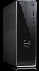
Back 1 Back panel Connect USB, audio, video, and other devices. 2 Expansion-card slots Provide access to ports on any installed PCI Express cards. 3 Power port Connect a power cable to provide power to your computer. 4 Power-supply diagnostic light Indicates the power-supply state. 5 Security-cable slot Connect a security cable to prevent unauthorized movement of your computer. 6 Service Tag label 11
Back 1 Back panel Connect USB, audio, video, and other devices. 2 Expansion-card slots Provide access to ports on any installed PCI Express cards. 3 Power port Connect a power cable to provide power to your computer. 4 Power-supply diagnostic light Indicates the power-supply state. 5 Security-cable slot Connect a security cable to prevent unauthorized movement of your computer. 6 Service Tag label 11


